Product Review: Sieg KX3 CNC Mill

With the development of the KX3 CNC milling machine, Sieg continues their trend of building on a good basic design to create new machines with advanced features.
In this case, the base machine is the X3 mill. From the X3 platform Sieg later introduced the more versatile and advanced Super X3, and now the CNC KX3 mill. But while the cast iron base, table and column are shared with the X3, the similarity pretty much ends there, as the KX3 is otherwise an entirely new and different machine.
A reader pointed out the at the base on the KX3 is not the same as the base used by the X3 and Super X3. While they are similar, the base for the two manual mills has an angled extension on the front-right corner for the Z axis handwheel.
CNC Machine Tools
In case you’re not familiar with them, CNC lathes and mills are similar to (and often derived from) conventional hand-operated lathes and milling machines, but are outfitted with computer-controlled motors on each axis.
The great thing about a CNC machine is that you can program it to produce complex shapes that would be difficult and very time-consuming to machine using manual controls. What’s more, once the program is written, it can be rerun indefinitely to produce as many identical copies of the workpiece as desired.
Better still, with modern CAD/CAM (Computer Aided Design / Computer Aided Manufacturing) software, you can design the desired part visually, in three dimensions, and have the CAD/CAM software produce the program instructions to make the part.
Not surprisingly, these attributes make CNC machines essential for modern, high-precision manufacturing operations. Unfortunately, because CNC machines contain complex and expensive electronic controls, motors, precision ball-screws and computers, they have been financially out of reach of most hobbyists and small businesses. Commercial CNC mills generally cost at least ten thousand dollars, and several hundred thousand dollars for larger and more advanced machines.
Of course this doesn’t deter the hard-core hobbyists who modify standard manual tools for CNC use. If you’re an experienced machinist, have a strong background in electronics and computers and lots and lots of spare time, creating your own CNC machine can be a rewarding and educational experience. But for someone who just wants to make complex parts, or perhaps run a small manufacturing business, investing a year or so building your own CNC machine may not be an attractive option.
Sherline offers some very nice CNC mills suitable for making small parts, such as for HO-scale model railroading or model ship-building. Similar machines are available based on the small Taig mills. These machines can be a great choice at an attractive price for those who only need to make small parts. If your interests tend towards larger creations, though, there are not many ready-made CNC solutions available that are affordable to the hobbyist.
That’s where the KX3 fits in. It fills a market niche for mid-size CNC machine that, while not inexpensive, is at least within the grasp of the serious hobbyist or would-be manufacturer. I’ll talk a little bit more about pricing in the Conclusions section.
General Construction
Based on the same frame and components as the Sieg X3 and Super X3 mills, the KX3, at around 500 lbs., is a formidable piece of machinery. That’s including the cabinet base, which contains all of the electronics, and contributes about 150 lbs. The marketing brochure lists the total weight as 220 kg, which translates to 484 lbs.
So, moving this puppy around the shop is a non-trivial exercise. You must have some specialized tools, common sense and, hopefully, some experience (or friends with experience) moving machines in the 200 lb.+ range before you tackle this one. If necessary, the mill can easily be removed from the base, to make transport easier. Regular readers know about the idiosyncrasies of getting heavy equipment into my shop. Delivery into the garage is easy, but getting from the garage into the shop never is. But, as they say, getting there is half the fun.
While the KX3 shares the same basic construction as the X3, there are some significant differences. Most noticeable is that there are no hand controls on the KX3. None. Zip. Zero. Well, that’s not absolutely true: there’s a power on/off switch and emergency stop button, but that’s about it. No X, Y and Z handwheels, no 3-spoke or fine-feed spindle control. In fact, no extendable spindle – since none is needed.
One really nice feature of the KX3 that sets it apart from some of the other mid-size mills is that the head rides on a dovetail column rather than a cylindrical post. The advantage is that, as it is raised or lowered on the column, the head stays precisely aligned with the work . Since the raising and lowering is all done by a stepper motor under computer control, there’s no need for an extendable spindle.

So, with no handwheels, how do you make adjustments during setup? In CNC, there’s a concept called jogging, which is moving the table and head, often by just a small amount, using push-button or knob-type controls. But before I get into more detail, I need to talk about the software that controls the KX3.
Artsoft Mach3 Controller Software
As important as the machine itself, is the software that controls it. CNC software traditionally has been a proprietary product developed by the tool vendor and works only with the tool it was designed for. As with most everything else related to computing, the PC has changed that concept.
Thus it was that Art Fenerty set out around 2000, to develop Windows-based CNC control software. From that effort, Art, with help from many others, has grown the Artsoft company and their CNC software product, Mach3, which now has over 10,000 users.
Art and his sidekick, Brian Barker, are busy adding enhancements and new features to Mach3 all the time, although I hear that Art is “retiring” from the business at the end of 2007 for a well-earned break.
Aside from the unusual way that it was developed, Mach3 is unique in that nearly everything is parameterized. That is to say, that rather than hard-coding the software for a specific machine or class of machines, just about everything about the machine is configurable.
Thus, Mach3 not only can run a mill such as the KX3, but can also drive lathes, gantry routers, plasma cutters, cloth cutters and just about anything else that involves precision control of a device that does cutting in a three-dimensional space. Thus, it is an ideal control platform for home-brew machines, each of which has its own unique characteristics.
Of course you’ll need a PC – and you’ll really want a dedicated PC for your mill. The good news is that just about any PC made in the last few years, with a CPU speed of 500 MHz or more and 256MB or more of RAM will run Mach3.
If you can’t scrounge one that your office is throwing away, you can buy a new one for under $400. While a CRT display will work fine, and could almost certainly be obtained for free, a flat-panel display is nice to have.
A cable provided by Sieg runs from the computer printer port to a DB25 connector on the front of the KX3. That’s the only connection between the two, so you can easily detach the computer and use it for other purposes.

I’m currently running Mach3 on a Dell X300 notebook computer. The notebook is mounted in a docking station which is where the printer port is located. A nice feature of this setup is that I can simply pop the laptop out of the docking station when I want to use it somewhere else for another purpose.
Not yet having decided what sort of stand to use for the laptop, or even if the laptop will be used in the final setup, I pressed a stepladder into service as Operator’s Console.

Because the Mach3 software takes control of the PC at a very low level, you’ll want to shut down Mach3 when using the computer for other work, or you may find that other processes run very slowly.
However, I’ve found that if I start the other processes first – such as Internet Explorer – I can use them even while Mach3 is running. On a few occasions, I have even transferred files using a wireless router, from another computer to the Mach3 latop, all while Mach3 was running (not actually doing any machining operations, though!)
I have sometimes noticed that when the spindle is running, even if it is not doing any cutting, it will slow down every once in a while. After investigating, I discovered using Windows Performance Monitor, that some process was taking up a lot of CPU resources on a regular cycle, about every 50 seconds.
I haven’t yet tracked down what’s causing this effect, but the lesson is that it’s probably best to have as few processes as possible running when you are doing machining, or, if possible, start all the other processes before starting Mach3.
Shown below is the main Mach3 screen. In the window on the left you see GCODE instructions for a program I wrote to surface a workpiece. Although I had some previous computer programming experience from more than 10 year ago, GCODE is simple enough that is easy to learn.
Mach3 makes it even easier, since you can enter individual GCODE instructions on the Manual Data Entry (MDI) screen (not shown) to see what effect they have.

As you can see, the screen is divided into several functional areas. The upper middle area shows the DRO’s (Digital Read Outs) for four axes, although only three are currently in use.
The upper right area shows a simulation, in real time, of the path taken by the cutting tool. The left section has buttons that control the execution of the GCODE, while the remaining three sections deal with tool, feed and spindle speed settings.
So many controls can seem intimidating at first, but they are logically laid out and you quickly get used to them after a little (careful) experimentation. In many cases, when you’re using predefined GCODE programs all you need to do is jog the axes to set the zero points.
Once that’s done, you start the program and the machine takes care of the rest of the operations. Once you’ve tested a program and are sure that it works as expected, you can let the machine work in the background while you attend to other shop business.
One thing I quickly learned about GCODE: you must be very careful with each instruction, as the machine may take off in a direction you don’t expect and break something. In spite of my being very careful as I was learning, I did manage to run a 1/2″ dia. mill into the top of the milling vise. Fortunately, no serious damage was done, but the vise now has a gouge in it to remind me to be careful.

While it’s not too difficult to write GCODE programs, in most cases you won’t need to do so. First of all, Mach3 includes a number of useful “wizards” for frequently performed operations such as milling a surface, cutting a pocket or drilling a bolt-hole circle. Mach3 is designed so that new wizards can easily be added as they are developed using MS Visual Basic. In fact, although it’s been more than ten years since I did any VB programming, I could see that it would not be too difficult to write a VB program to accept input parameters and then generate a GCODE program as output.
Then again, much (most?) of the work that you do on a CNC machine can be done without any programming at all. The key is to use CAD/CAM programs to design the parts that you want to make and automatically generate the GCODE as output. Then load the GCODE into Mach3 and away you go! I haven’t gotten that far in my own CNC education so far, so I can’t say much more about it at this time. Maybe later.
Also, if you run into questions or problems, there’s an online forum of Mach3 users who can help you out.
CNC Drive Motors & Electronics
Controlling the stepper motors for a CNC machine is somewhat complex, requiring specially designed electronic drivers. Again, for the uninitiated, stepper motors are special-purpose, DC permanent magnet motors that are driven by electronic pulses, typically up to several amps from anywhere from 12 volts up to a hundred volts or more.
Each pulse typically rotates the motor shaft by 1/200 revolution, or 360°/200 = 1.8°. A technique called micro-stepping can move the shaft in even smaller increments.
Depending on the ratio of any intervening gears (none in the case of the KX3) and the pitch of the driven leadscrew, table motions of under 1/1000th” are typical. However, when driven by a steady stream of pulses, the motors can rotate rapidly enough to advance the table quickly in the desired direction of travel.
In their stopped state, the magnetic field of the motors locks them in place, holding the non-moving axes firmly in position.
Stepper Motors
The stepper motors (NEMA34 class according to the Sieg KX2 brochure) on the KX3 are large and powerful. As an example, I can drive the table along the X axis at about 1 inch per second.
In fact, using the motor tuning screen in Mach3, I can set the motors to move even faster, but, for now, until I gain more experience and confidence with the KX3, I decided to use a moderate mid-range speed. This approach gives me more time to react and hit the “panic button” if things aren’t moving where they should be.

With CNC control, a simple coding error can drive the mill to do things that you don’t want it to do – such as drive the tool into your vise. The machine “knows” where it is, where you told it to go, and how fast, but it can’t see or react to obstructions that might be in the way.
One thing it does know, is when it has reached the limit of travel in any of the three axes. It knows this because each axis is equipped with a pair of roller-type limit switches that are triggered when the table (or the head, in the case of the Z axis) reaches the limit of travel.
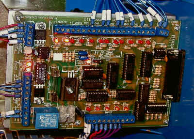
Electronics
Solidly constructed from heavy-gauge sheet metal with abundant bracing, the cabinet supports the mill while providing a convenient housing for the drive electronics. A door with a key-lockable handle occupies most of the left side of the cabinet and opens wide to provide access to the electronics inside.

Power Supply
A massive transformer drops the AC line voltage down to 50 V AC that feeds into a bridge rectifier and filter capacitor to provide the raw DC power for the electronics. A secondary power supply module, in the ventilated box on the lower right, provides supply voltages for the parallel port interface card (also known as the Break Out Board, or BOB) just above. More about the BOB in a minute.

Stepper Drivers
Three stepper motor driver modules, for the X, Y and Z axes, respectively, occupy the upper part of the supply board. Looking back at the photo above, you’ll see that there’s a fourth stepper driver mounted on the lower part of the panel. It will drive an optional fourth axis rotary table that Sieg is developing.

Wiring Connectors
As seen in the photo below, all wires are routed through wiring channels to present a neat appearance and to keep them from getting snagged on anything.
All connections from the electronics are routed to a barrier strip where they connect to leads from plugs in the back of the base cabinet. From there, the plugs join with mating sockets on the back of the mill. Each of the four plugs is a different size, making it simple to match them up and avoiding any potential confusion about what connects to what.
The plugs also make it easy to remove the mill from the cabinet, as you may find convenient or necessary when moving the mill into your shop or transporting it by truck or van. Each socket has a tethered screw-on cap to keep dirt, dust and chips out of the sockets during transport.

A small fan draws cooling air through filtered intakes on the lower front and back of the cabinet and expels it out the top of the back of the cabinet. With the cabinet door closed, the mill is very quiet when just idling – the only sound coming from the fan.
Break-Out Board
The Break Out Board (BOB), a cnc4pc.com model C11G, is a specialized circuit card that interfaces the drive electronics to the computer printer port. The name derives from an old electronics term that refers to an interface between two devices that “breaks out” the connections between them to provide access for monitoring the logic state of each connector pin.
When configuring the interface between a CNC device and the Mach3 software, being able to see the logic state of each interface pin is a huge advantage. Opto-isolators are used on several of the pins to protect the PC parallel port from voltage surges that could be induced by the stepper motors.
The KX3 comes factory-configured for Mach3, so normally there is no need to be familiar with the function of the BOB. Unfortunately, the machine that I’m reviewing was treated very roughly by the shipping company, resulting in some damage and some wires being knocked loose.
To resolve the wiring problems, I took digital photographs of the LED’s on the BOB and emailed them to the Sieg engineering team in Shanghai. Based on the LED’s, they were able to quickly identify the problem and email me instructions on how to fix it. Cool.
Head and Spindle
Like the rest of the KX3, the head has a clean appearance, since the only control is the red Emergency Stop Button (ESB), prominently mounted and easily reachable on the front of the head.
On the left side, we find the power cable for the spindle motor, encased in a flexible protective sheath, and the hinge for the spindle shield. The shield is constructed from polycarbonate plastic – the same stuff that bulletproof windows are made from. While tough, it won’t take a bullet for you.


The hinge looks larger than necessary. That’s because, hidden inside, is a switch that sends an Emergency Stop (Estop) signal to Mach3 when the shield is open. Although it looks like a chip shield, its true function is as a safety interlock to ensure that the mill is shut down when you’re changing tools or making adjustments to the spindle. A magnetic catch holds the shield in the closed position.
Motor and Belt Drive
Tucked way down inside the head, the motor is not accessible for photographs. However, I’m pretty sure from what I could see, and from the Sieg KX3 marketing brochure, that its the same type of 1000 watt DC motor that powers the C4 lathe. The motor drives a cogged pulley that in turn drives the spindle shaft via a toothed timing belt.

This is a nice design, as mini-mill owners will be quick to realize. In the mini-mill, the coupling is done with gears, which have an unfortunate habit of losing teeth if the tool is driven too deeply into the workpiece. As a bonus, the belt drive is much quieter than gear drive.
Emergency Stop Button
When pressed, the ESB immediately stops the X, Y and Z stepper motors and the spindle motor and locks into the OFF position. When I’m testing new GCODE programs, I’ve found it prudent to keep my hand close by the ESB so that I can quickly shut down the mill if it heads off in an unexpected direction.

This can sometimes get exciting. When doing conventional (non-CNC) milling, you typically have your hand on one of the axis handwheels. Other than when using powerfeed, you usually have complete and immediate control over the feed and can simply stop turning the handwheel if something doesn’t look or sound right.
Plus, you are almost always moving just one axis at a time. Not so with CNC: depending on the GCODE commands driving the mill, all three axes can be moving at the same time, and at a faster rate than you would achieve using a handwheel, so potential emergencies can develop quickly.
The ESB sends a stop signal to the Mach3 software which terminates any GCODE that may be executing. To restart, the ESB must be twisted clockwise, which releases the locking mechanism and returns the button to its normal position.
In addition, there is a logical ESB, or RESET, button on the Mach3 screen which must be reset by clicking on it. Alternatively, you can press the tilde (~) key on the keyboard. The logical RESET can be triggered by a number of events including pressing the ESB, opening the spindle chip shield or hitting any one of the X, Y or Z limit switches.
Spindle & Collets
Unlike the X3 and Super X3 mills which have an R8 taper spindle, the KX3 spindle uses an OZ25 standard collet chuck. Both inch and metric collets are available. Since all of my tooling is in inches, I am using the inch-type collets; a complete set of which were provided by Sieg.

To mount a collet in the collet chuck, you unscrew and remove the outer sleeve of the chuck. A hex wrench is inserted into the top of the spindle shaft and held in place to prevent the spindle from turning. No drawbar is needed or used.


Due to their notched design, the collets are “springy” so that they can close tightly onto the tooling, and snap into a ring machined into the recess of the sleeve. With the collet snapped into place, the sleeve is screwed back onto the threaded spindle. Then the tool is inserted and the the collet sleeve retightened using the two wrenches.

When working with CNC, it is desirable to know the exact distance that a particular tool extends from the collet. If this dimension is known, then when changing tools during the course of a CNC program, the Mach3 software can automatically compensate for the varying tool lengths, thus eliminating the need to re-zero the Z axis.
The OZ25 collet chuck has no built-in stop to hold tools at a known position, but it looks to me like it would not be difficult to improvise one.
Table
The table casting is 21-1/2 x 6-1/4″ , with a usable work surface of 18 X 5″ (460x130mm). There are three T-slots that use 12mm T-nuts. 7/16″ T-nuts also work perfectly well.
Surrounding the table is heavy-gauge black sheet metal enclosure. Although it helps to keep chips from being thrown around the shop, its primary purpose is to capture and recirculate coolant. While no coolant pump was provided with the machine I’m reviewing, I noticed that Sieg advertises one in the KX3 promotional brochure.

Used coolant collects in the bottom of the table slots and drains out a threaded hole in the back left corner of the table. From there, it can be captured by a hose and returned to the coolant reservoir, or drained into the top of the pedestal base, which has its own drain in the back right corner.
The front of the containment tray has a hinged door, locked in the closed position by ball-spring detents on either side, that opens downward to provide better access to the table for setup operations.

A potential disadvantage of the coolant capture tray is that it precludes using a milling vise or other work setup that extends past the front of the table. The milling vise must be mounted lengthwise on the table.
Should this become a problem, the coolant tray can be removed in a minute or so by using a power screwdriver to remove the 10 cross-head screws that hold it in place. If you find yourself needing the remove it often, you could just leave it off, or just use 4 screws to hold it in place.
Limit Switches
Each of the X, Y and Z axes has a pair of limit switches with roller / lever actuators. The switches are fixed in position and are activated by adjustable limit stops that move with each axis.
Rounded corners on the limit stops engage the switch rollers to trip the switch, thus stopping the motion of the table (or the head, in the case of the Z axis.) The limit stops are mounted on L-brackets attached to each axis, and can be moved by loosening their retaining screws and sliding them along a groove in the L-bracket.
Normally, metal covers protect the switch housing from falling metal chips; I’ve removed the cover in the photograph below to show the mechanism.

Once they’re set at the factory, typically to allow the maximum range of motion for each axis, there should be no need to move the limit stops. On the machine that I’m reviewing, with the limit stops as far apart as possible, the X-axis could move only about 8″, rather than the full range of 11 1/2″.
Never one to miss an opportunity to make modifications, I used the mini-mill to extend the grooves in the bracket and drilled new mounting holes offset by 1 3/4″ from the old ones. These changes increased the X-axis range to 10 1/4″. With a little more finagling I could get the full 11 1/2″ range.
X, Y and Z Movement
Ball Screws
Ball screws are commonly used in CNC machines because they offer two important advantages: very low friction and very low backlash. The key to both is the use of precision ball bearings in a recirculating track, that engage with the lead screw where a nut normally would be used.
Shown below is a section of the X-axis ball screw and the ball nut. Note the feed from the one-shot oiler system, described below.

A similar, but smaller, ball screw is used for the Y axis. Another oil port keeps it well lubricated.

One-Shot Oil System
Since CNC machines tend to move more rapidly and for longer periods of use than manually operated machines, lubrication of the dovetails and other key moving parts is essential. Sieg has incorporated a single-shot oiling system in the KX3 which makes lubrication a quick and simple task: just grasp the handle on the oiler, draw it back, then release it.
On the return stroke the oiler distributes the lubricating oil through a system of flexible tubing to all of the vital moving parts. The flexible tubing is a tough plastic sheathed in a flexible metal outer jacket to protect it from wear.

Channels are machined into the ways to distribute the lubricating oil across the surfaces that move. Oil feeds through the one-shot system into these channels.


Dovetail Covers
Protective covers on the Y and Z dovetails are another nice feature. No cover is needed on the X-axis dovetails, since they are shielded by the table. On the Y axis, the dovetails are covered by a telescoping set of stainless steel boxes that move in and out with the table along the Y axis. The Z axis is shielded by a heavy-duty accordion-style cover.

Conclusion
For the experienced mill user looking to move into CNC work, the KX3 provides a ready-to-go solution. The KX3 is now available in the US from Harbor Freight (SKU 66051) for $4999.99.
While not as fully automated as large, industrial-class CNC mills, with appropriate jigs and fixtures and an efficient work plan, this mill should be capable of turning out profitable work for a small business operation.
For the hobbyist, where’s there’s more freedom to pursue whatever interests you, and no pressure to make a profit, the KX3 can open up new areas of exploration, and make it possible to create curves and complex shapes that just can’t be done effectively on a manual mill. Who knows, you just might come up with something that leads to a profitable business venture.
Sounds like a lot of money, but, if you consider the number of hours and dollars you’d spend to do your own conversion of an X3 mill, it starts to look like a bargain, if you place a reasonable value on your time. Plus you need to consider the value of the hair that you’ll pull out while trying to get your home-brew machine working!
To put the price into perspective, consider that back around 1975, when I started my first part-time business, I paid about $2000 for the Enco Maximat 7 lathe/mill. That was about 3 months pay for me, back then. Fortunately, I had a very understanding wife, and she’s still with me to this day, wondering when I’ll have enough tools.
