Sieg Super X3 Mill
 Sieg Super X3 mill
Recently arrived at mini-lathe.com World Headquarters is the Sieg Super X3 mid-size mill. I’ve been hearing about it on the internet for a while and was excited when the opportunity to test one emerged.
Well, it arrived recently, and I’ve had a chance to set it up, but have not done a lot of testing so far. Operations at mini-lathe.com & mini-mill.com tend to scale back during the summer months as I, and my readers, enjoy spending time outdoors with their families and friends.
So, to get the full scoop, you’ll have to come back again, say around the end of August, when I have more time to spend in the shop. But for now, here’s a small sample of what to expect…
There’s been some controversy on the web about the Super X3 being under-powered. I don’t have the full story on this, and there may have been some early models for which this was true, but the one I’m testing now seems to have plenty of power - even though the motor is fully enclosed in the head.
Take a look at this 0.100" depth cut using a 1/2" end mill - it powered through this test like a mole digging through soft dirt.

I did some more tests using a 3/4" 4-flute end mill on the same block of aluminum and found that a cut at a depth of 0.060" was no problem, while at 0.080" depth, the mill would whine and growl.
This does not seem to be a limitation in the power of the motor so much as reaching the stress limit of the spindle assembly, since I did not notice any tendency for the motor to bog down.
Since I have the Super X3 sitting side-by-side with the X3, I hope to do some comparison tests on power, as well as other features of the two models, and give you the full story.
What the two models have in common is their basic framework, including the base, column, X- and Y-axis controls and table. Where they differ is in the construction and features of the head assembly, Z-axis feeds, the motor and the control electronics.
And therein lies a whole lot of interesting news. Take a look at the heads of the Super X3 and X3 below and you’ll get the idea…


Among the more obvious differences on the Super X3 are the following features:
- Digital RPM (tachometer) display with Forward / Reverse indicator
- Push-button membrane control panel
- Fine Feed control knob (similar to that on the mini-mill - only better!)
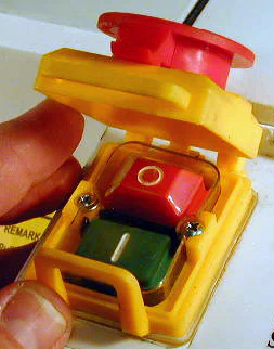
- Emergency Stop button moved from outboard box to front of head
- Power-on pilot light
- Digital Height Gauge continuously displays spindle advance
- Reverse and Tapping mode control buttons
Of course you’ve already heard about the tilting head feature, right?

But what about those green buttons on the ends of the three-spoke handles? What’s that about?

Well, I hope that’s enough to stimulate your interest for now. Thanks for stopping by, and stay tuned for the full story!
Part 2: More of the Story
Busy with the usual outdoor activities of summer, I haven’t had much time to do any further testing on the Super X3 mill since the last installment (07/25/06).
However, I promised an update by the end of August, so I’ve added some new material. There’s still a lot more to come, and I’ll do my best to provide weekly updates during September.
Since the construction of the base, column, table and X-,Y- controls on the Super X3 are identical to those on the X3, I won’t repeat that information here.
Instead, I’ll focus on those features that differentiate the two models.
Tilting Head Assembly
First, let’s take a closer look at the new tilting head feature. Regular readers may remember that I am not a big fan of tilting heads in general, and as implemented on the mini-mill in particular.
On the mini-mill, the head is tilted by loosening the BIG NUT at the base of the column and then rotating the entire column/head assembly left or right as needed.
One problem with that design is that you have to swing the head pretty far over to achieve, say, a 30 angle to the table. In the process, the head is shifted towards one end of the table or the other, and closer to the table, limiting the range of vertical movement.
Secondly, any time you move the head in this way, you are faced with a time consuming (10-20 mins.) process called tramming, to accurately realign the head square to the table. For these reasons, I much prefer the simpler solution of using a tilting vise.
I like the tilting head feature of the Super X3 a little better:
- Head is tilted relative to the column; column remains bolted in place
- Spring-loaded pin locks the head at 0 and 90 positions
To tilt the head, loosen the two “chrome dome” nuts.
 Tilt instructions (slightly tilted) on side of head

 “Chrome Dome” nuts
Before you move the head, you must first release a locking bolt by inserting a 6mm hex wrench into the bolt head and twisting it clockwise about 45.
The locking bolt is spring loaded and will revert back to its original position when you remove the torque, so you must maintain pressure on it until the head is moved away from the 0 position.
 Head lock release access hole
Grasp the head firmly and tilt it to the desired angle, using the protractor on the side of the head as a guide. If you’re shooting for an angle other than 90, you will probably need to tap the head lightly with the open palm of your hand, or a dead blow hammer, to get the setting right on the mark.
Then tighten up the two chrome dome nuts, and you’re good to go.
As an illustration, I cut a 30 and a 45 V-notch into the aluminum block that I’d been using for test cuts. Of course, due to the angle at which the cutting tool ends up, you can only cut using the cross-feed to advance the tool across the workpiece.
Another factor to keep in mind is that when the head is tilted, you generally will lose the convenience of being able to use the fine spindle advance and the digital depth indicator.
 30 and 45 “V” grooves
No doubt there are applications where this would not be true, but in the example I tested, I wanted the point of the “V” to be at a specific location. (In truth, it didn’t really matter for this test, but I was thinking of a real application I had done in the past, where I needed to cut a V-groove at a specific location on a workpiece.)
I you advance the tool using the spindle, rather than the Z-axis leadscrew, the edge of the tool that forms the base of the “V” moves to the right as it moves deeper.
With a little trigonometry, I suppose that I could figure all this out and make it work, but I find it easier just to use the Z-axis leadscrew.
One other consideration when using the tilting head feature is that the cutting tool swings out away from the center of the table. If you’re milling vise is centered on the table, you’ll have to move the table out to the right to compensate.
Alternatively, you could relocate the vise towards the right end of the table.
 Table moved far to the right
The other way to do angled cuts, and the one I usually prefer, is to use a tilting vise with an angular scale. The particular vise I have been using this way is really a drill press vise rather than a true milling vise, but is heavy enough to handle work on the mill.
I like using the vise, because, depending on which way I orient it on the table, I can use either the X- or Y-axis feed. So, if I really needed to, I could cut a V-groove or beveled edge as long as the X-axis traversal (about 16").

Maybe there are advantages to the tilting head that I have not yet discovered. There may be experienced machinists reading this who are chuckling because I’ve missed something obvious.
But until they contact me, or I discover it on my own, I will continue my prejudice for using an angle vise.
In any case, the only downsides that I can think of are that the tilting head may add some cost and slightly reduce the rigidity of the mill.
Who, knows, maybe it will come in handy some day, in conjunction with the tilting vise, when I need to cut a compound angle.
The good news in all of this I think is this: if you have already bought the standard X3 mill and are longing for the tilting head feature, just go buy yourself a good angle vise.
On the other hand, if you have bought the Super X3, or are thinking of doing so, you may find this feature useful (but buy yourself a good angle vise anyway ;-)
Z-Axis Fine Feed Control
Readers familiar with the mini-mill may recognize the fine-feed control as similar to the one on the mini-mill. Well, it is and it isn’t. It is in the sense that it performs a similar function.
It isn’t in that it is much more precise than the one on the mini-mill, having much less of the backlash so prevalent on the mini-mill version. I’m not sure how this new one is engineered internally, as the parts explosion diagram in the manual is small and a little difficult to interpret in detail, and I did not feel inclined to disassemble the drive train.
I can, however, report that it is smooth and precise in operation, with very little (maybe a 16th of turn) of backlash. In any case, since on the Super X3 you have a direct-reading digital scale built into the headstock, backlash becomes pretty much a non-issue.
 Handwheel for fine Z-axis movement
As on the mini-mill a three-spoke downfeed handle provides coarse movement of the Z-axis - particularly suitable for drilling operations where quick motion is desired, but precision vertical positioning is not a factor. However, the mechanism on the Super X3 mill is entirely different than that on the mini-mill.
On the mini-mill, the handwheel moves the entire head assembly up and down the column using a rack and pinion arrangement. By contrast, on the Super X3 mill, the head remains stationary, with a separate quill assembly being the moving component.
This latter arrangement is more typical of that found on industrial mills such as the famous Bridgeports.
 3-spoke downfeed handle for coarse Z-axis movement
Tightening or loosening a small handwheel that is mounted coaxially with the hub of the 3-spoke handle engages or disengages the fine-feed. A quarter turn or less is enough for either operation, so I’m a little perplexed as to why the handwheel is outfitted with a folding handle - as you would find in an application where many turns might be required.
Such mysteries are too deep for me.
(Update 01/06/11 - having done more work with the mill now, I have found that the purpose of this handle is to provide extra leverage when tightening and loosening the handwheel, with the handle folded out all the way so that its parallel with the wheel)
 Handwheel engages fine-feed
And what about those mysterious green buttons on the ends of the downfeed handle spokes? What are they for? Patience. We’ll get to that soon enough.
Z-Axis Movement Controls
Let’s take a closer look at the vertical (Z-axis) movement controls. In practice, you have three different ways to move the cutting tool up and down:
- Z-axis handwheel - moves the entire head assembly
- 3-spoke downfeed handle - coarse movement of the quill
- Fine-feed handwheel - fine movement of the quill
On my older Sieg X3 mill, the weight of the head is partially offset by a gas strut - similar to those used on hatchback cars - but that component is not included on the Super X3 or on current X3 models.
According to a Sieg representative, they eliminated the gas strut because it prevented the head from moving over the full range of the column. A quick test showed that on my X3 mill, the face of the spindle can be moved no closer than 5 3/4" to the table, while on the Super X3, the spindle can be cranked down until the spindle face touches the table.
 Head cranked all the way down
Without the gas strut to offset the weight of the head (about 50 lbs.), something had to be done. The Z-axis handwheel drives a shaft terminated by a bevel-gear that engages with another bevel gear that drives the Z-axis leadscrew.
On the X3 with the gas strut, these two bevel gears are both the same size, with a 1:1 gear ratio. On the X3/SX3 models without the gas strut, one of the gears is larger, providing a 1:2 reduction ratio.
Naturally, this helps to reduce the amount of force required to turn the handwheel, but the head moves only half as far (0.050") per turn as on the older model (0.010").
Therefore, while each division on the dial of my older X3 represents 0.001 (a nice convenient number), on the newer models each division represents 0.0005" (a half-thousandth).

 Old and new calibrations
So there’s a tradeoff here. Without help from the gas strut, the newer design requires noticeably more force to crank the head upwards, and takes twice as many turns of the handwheel to raise it a given amount, compared to the older design.
On the other hand, the older design gives you less range of movement.
One way to get around this is to rig up some counterweights and pulleys to offset the weight of the head. At least one owner, Bruce Murray, has done this and has posted some plans
(Note: link is a PDF file and may take a while to load) in the Files folder of the Lathemaster group on Yahoo.
(Note: you may need to join the group to access this document). It may also be feasible to find and adapt (externally?) a gas strut with a longer range of movement than the one originally used by Sieg.
Another possibility, that I hope try before too long, is to add a motorized drive to the Z-axis; however the motor will need a very high starting torque.
Since most of my use of the mill is done using the milling vise, I find that once I set the head to a convenient height above the vise, most adjustments can be made using the quill rather than moving the head.
Quill and Digital Height Gauge
The quill is similar to that on the X3, but has a slightly different profile; both have an R8 spindle taper. The big difference is that the quill on the Super X3 is directly attached to the Digital Height Gauge (DHG) built into the head and has a fine-feed handwheel separate from the spindle downfeed handle.

 X3 & SX3 Spindles
There are five control buttons on the front face of the height gauge:
- On/Off
- Zero - sets the readout to zero
- mm/in - toggles between inch and millimeter measurement mode
- Plus
- Minus
I’m embarrassed to admit that I can’t recall how the Plus and Minus buttons are used. Somewhere, years ago, I used similar buttons on a digital display, but their function escapes me at the moment and no documentation was included with the mill to educate me.
I’m pretty sure that they are used for measuring relative to a fixed point.
 Digital Height Gauge
If you are not familiar with them, a DHG has a sliding arm - in this case having one end attached to the quill - that is encoded to digitally display the extension of the arm in increments down to half-thousandths of an inch (0.0005") or hundredths of a millimeter (0.01 mm).
The display is powered by a small button-type battery under the cover at the lower right of the front panel. Typically, based on my experience with other similar displays, the battery will last for a year or more, even if the display is left turned on.
Let’s say you need to mill a 1/4 slot in a workpiece to a depth of 0.020". First move the surface of the workpiece under the tip of the cutting tool, then use the three-spoke downfeed handle to lower the quill until the tip of the cutting tool touches the surface of the work.
Turn the handwheel at the center of the downfeed handle to engage the fine-feed; this locks the quill at the current height.
Press the Zero button on the DHG to establish a zero reference height at the surface of the workpiece. Move the table so that the workpiece is out from under the tool, then use the fine-downfeed handwheel to lower the quill until the DHG reads 0.020".
Now you can mill the desired groove with confidence that it will be exactly the right depth. (Note: as a matter of good technique, if the groove needs to be exactly 0.020" deep, this operation would better be done by first making a roughing cut of about 0.018, followed by a finishing cut of 0.002".)
Having a built-in digital display is a nice feature. On my mini-mill, one of the first modifications I made was to mount a dial indicator on the Z-axis to gain a similar capability.
It has turned out to be indispensable
Push Button Controls and Digital RPM Display
 Head controls
Prominent on the front of the head is a push-button control panel with the following buttons:
- Up Arrow - increases spindle speed
- Down Arrow - reduces spindle speed
- Start - starts the motor and spindle rotation
- Tapping - toggles Tapping mode
- Forward - sets Forward (clockwise viewed from above) spindle rotation
- Reverse - sets Reverse (counter-clockwise) spindle rotation
- Stop - stops the motor and spindle rotation

Just above the push-button panel is a digital RPM display (tachometer). The display has cool blue backlighting with good contrast under normal shop lighting conditions.
The display also has three mode indicators on the right side:
- FORWARD - displayed when rotational direction is set to Forward
- REVERSE - displayed when rotational direction is set to Reverse
- STOP - displayed when motor and spindle are stopped

When the mill is powered on using the rotary switch on the side of the column, the motor is stopped and the RPM display reads all zeros with mode indicators of FORWARD and STOP.
Pressing the UP ARROW (speed) button starts the motor and the RPM display settles out at around 200 RPM. Pressing the UP ARROW button repeatedly increases the spindle speed in increments of about 20 RPM.
You can also hold down the button, which increases the speed steadily up to the maximum speed of about 1820 RPM (1750 nominal as specified in the manual).
Pressing the DOWN ARROW button, as you might guess, has the opposite effect.
The Stop button quickly stops the motor and spindle rotation. Evidently, electronic braking is applied, as the spindle will come to a stop from its maximum speed in less than two seconds.
If you now press Start, the motor will resume the speed that it was at when you pressed Stop.
You might reasonably assume that pressing the Reverse button reverses the direction of spindle rotation, and you’d be correct, but it does so only when the motor is running.
That’s right, pressing the Reverse button (or the Forward button) has no effect when the motor is stopped, but has the expected effect when the motor is running.
OK, so let’s say that the spindle is spinning at top speed and you press a button to reverse the direction of rotation. Smoke comes pouring out of the motor while a terrible grinding sound tells you that gear teeth are being sheared off, right? Nope.
Instead, the intelligent motor controller automatically reduces the motor speed until the direction can safely be reversed, then it reverses the motor and accelerates the motor back to its original speed.
Pretty cool, huh?
Tapping Mode
Now let’s take a look at Tapping Mode. Finally, we’ll find out what those little green buttons on the downfeed handwheel are for!
On the end of each of the downfeed handles is a green pushbutton:
 Tapping mode reversal button
When the mill is in Tapping Mode, pressing any one of the three buttons instantly reverses the direction of spindle rotation. Tapping Mode is initiated by pressing the Tapping button on the control panel while the motor is running.
Here again, pressing the control panel button has no effect if the motor is stopped.
In Tapping Mode, the minimum spindle RPM is 100. This is a good fact to remember, since the minimum speed in “regular” mode is 200 RPM.
You may find a need someday to run at the lowest possible speed even though you are not doing a tapping operation.
The maximum RPM for Tapping Mode is specified in the manual as 500 RPM, but I found that by pushing the up-arrow button you can increase the speed all the way up to 1800 RPM.
Needless to say (I hope!), you don’t want to be doing tapping at that speed; personally, in fact, I can’t imagine tapping even at 200 RPM. And therein lies some food for thought.
If you’ve done much tapping by hand, you have probably had the experience of breaking a tap off in the workpiece. When that happens, it really is no fun at all.
Normally mild-mannered, I have been known to resort to profanity in this situation! The problem is that taps can easily seize in the work, so going slowly, and feeling the cutting action of the tap as you work the handle, helps you to know when the tap is bogging down and needs to be backed out to clear the chips.
Using power-feed, you lose this tactile feedback. Add the fact that the spindle turns the tap much faster than you can turn it by hand, and you have a potentially problematic situation.
 Tapping aluminum using the drill chuck
I made a few tests using a reasonably good quality 1/4-20 import tap mounted in the drill chuck. I started the hole using a center drill, then drilled to a depth of 1" with a #7 drill - the standard tap drill for a 1/4-20 tap.
Next I mounted the tap in the drill chuck and securely tightened the chuck. I applied a liberal dose of cutting fluid to the tap and the workpiece.
I started the mill by pressing the UP-Arrow speed button, then pressed the Tapping button to invoke Tapping Mode, and lowered the speed to the minimum of 100 RPM.
I lowered the tap using the downfeed handle until the teeth of the tap took hold, then let the cutting action of the tap draw it into the hole.
After a few rotations (which happens pretty fast at 100 RPM) I pressed the green button on the downfeed spoke to reverse the tap and back it out of the hole.
When backing the tap out, I kept a loose grip on the downfeed handle to keep it from snapping around when the tap broke free from the workpiece.
I repeated this test three times and had some success, but on the first two attempts, I stripped the threads before I was done.
The difficulty seems to be in ensuring that the tap re-engages with the threads already cut when backing out and restarting the cut.
On the third attempt, I was careful not to let the tap disengage from the threads when backing it out.
Another difficulty, given the relatively fast speed at which the tap advances into the work, is to avoid bottoming out the tap by running into the bottom of the pilot hole.
That’s the main reason why I made the hole as deep as I did (1"). Fortunately, the digital depth gauge gives you a reading on how deep the tap is - or it can, at least, if you remember to zero the depth gauge when the tip of the tap is at the surface of the workpiece.
Of course if you are tapping the holes all the way through the workpiece, bottoming out the tap is not a concern, so in that situation the power tapping could be a time saver if you have a lot of identical through-holes to tap.
One other problem that I ran into is that the tap would work loose in the chuck, even though I firmly tightened the chuck using all three chuck key positions.
When the chuck works loose, it is necessary to stop the mill, retighten the chuck onto the tap, then restart the mill. Using a collet to hold the tap might resolve this tendency.
My conclusion is that the power tapping feature could prove to be a useful time-saver if I had to tap a bunch of holes to the same size. I can’t really imagine using it, though, with a tap smaller than 1/4" diameter.
My advice to new Super X3 owners would be to do a lot of practice with this feature before you attempt to use it on a workpiece that you can’t afford to mess up.
Summary
With its larger size and greater power, the Super X3 opens up a range of work beyond what the mini-mill can handle.
While it’s similar in size to the X3, the more powerful motor, tilting head, fine-feed quill control and built-in spindle-speed tachometer make this machine a step up.
Due to the more powerful motor the Hi/Lo speed range control found on the X3 is not needed on the Super X3. In addition to being a powerful mill, the Super X3 doubles as a fine precision drill press.
Currently (2010) the Super X3 is available from Grizzly and Travers Tool.