Review: Sieg C8 Lathe

Introduction
Recently arrived at mini-lathe.com world headquarters is the new Sieg C8 lathe. In development for some time, the C8 has now joined Sieg’s growing family of machine tools.
Bigger and badder than the C4 and even the C6, the C8 could well be classified as a light industrial lathe. Marketed mainly for the hard-core home machinist, the C8 would also be suitable for use in a repair shop or prototype lab. Even compared to the C6, a formidable lathe in its own right, the C8 is a significant step up in size, weight and features.
Here are some of the features…
- Heavy construction – 200 kg, 440 lbs.
- Capacity – 280×750 mm, 11×30″
- Induction hardened ways
- Full-length T-slots in cross-slide table
- Knob-selectable power feed and power cross-feed
- Separate drive shafts for threading versus power feed
- Lever-lock tail stock
- Way wipers to keep chips from under the carriage
- Extending-coil leadscrew covers
- Quick-change gearbox for thread cutting
- Carriage and cross-feed lock screws
- Overload clutch on drive shaft
- MT 4 spindle with 25mm (1-inch) through hole
- Two models: traditional AC induction motor, brushless DC motor
- Optional add-on mini-mill milling head
So lets take a closer look at this beast, but, before we get started, I’d like to apologize for any small scrapes, dings or oil stains that may be visible in the paint or on other surfaces.
Usually, when I review a machine, I take all the photos as soon as possible after unpacking it, before normal use creates the inevitable scrapes and scratches that are a fact of life in a working shop. In the case of the C8, I used it for about two months before I got around to taking the photos. Rest assured that, fresh from the factory, Sieg’s products are nicely finished.
Bed and Ways
A significant part of the 440 lbs. (200 kg) of the lathe’s weight is attributable to the cast iron bed. Measured from end to end, the bed is 51″ (1295 mm) and the ways, measured from the headstock are 42.5″ (1080 mm) long.
The maximum distance between centers held in the headstock and tailstock is 30″ (750 mm.) Thick cross-ribs along the length brace the bed to resist twisting or flexing under the strong cutting forces that a lathe of this size imposes on it. With a bed this long, stiffness is essential.

This, as far as I know, is the first model of lathe from Sieg on which the ways are hardened. You still should take care, of course, not to drop tools, chucks or chunks of metal on the ways, but if you do so accidentally, the chance of leaving a dent or ding in the ground working surfaces of the ways is much smaller on this model lathe.
Free from such imperfections, the ways smoothly and accurately convey the carriage to do its work.

As on the smaller C2 through C6 lathes, the ways are of a double-prismatic design: raised guides with a triangular prism-shaped cross-section are cast into the front and back of the ways and are precision-ground to ensure that the carriage and tailstock remain accurately aligned with the lathe centerline as they travel along the ways.

On the back of the bed, you’ll find a flattened area on the casting with four threaded bolt holes. This is the attachment point for the optional C2 mini mill head which converts the C8 into a lathe-mill combination machine sold as the model M8. Sieg has used this strategy with several of their lathes and mills, building extra flexibility into their product line.

A sturdy sheet metal chip shield, painted gloss black, is set back about 12″ (300 mm) from the bed to allow room for the mini mill attachment. It does a pretty good job of preventing chips, oil and cutting fluid from launching from the back of the lathe onto a wall or whatever might be behind the lathe.
Head, Spindle and Chuck

Head
The head, supporting the spindle and spindle bearings, is another heavy casting. A recess in the front part of the head forms an enclosure for the electrical controls and associated wiring.

Looking down at the top of the head we see two square access panels. The front panel provides access to the spindle and interlock switch; the back panel opens into the motor compartment which is constructed from heavy-gauge sheet metal attached to the back of the head casting.
The steel plate shown below on the front panel did not come with the lathe – I glued it into the recess to make a convenient area for holding magnetic base indicators – my first modification to the C8 (and, no doubt, the first of many).

With the front top panel removed, you can see the spindle shaft mounted between bearing races. The white pipe encloses wiring running from the control panel to the rear access panel, shown on the right below.
Behind the spindle is the interlock switch that cuts off power to the motor when the spindle safety cover is raised. Looking down into the rear access area, you can see the motor, AC power safety switch and outlet for the optional milling head.


Spindle
Machined from a single piece of steel, the spindle forms the mounting plate for the chuck and runs through the bearings in the headstock out to the drive gears on the left side of the headstock.
The C8 spindle looks and functions very much like the spindle on the smaller C6 lathe, but, unlike its smaller brother, which features a #2 Morse Taper with a 3/4″ (19mm) through-hole, the C8 has a #3 Morse Taper with a through-hole slightly larger than 1″ (26mm). Naturally, a larger through-hole is an advantage when passing long stock through the hollow spindle.

As on the C6, the chuck is secured by studs that slide through the holes in the spindle on through the rotating plate on the back side of the spindle plate.
I found the fit of the studs to be more snug than on the C6; enough so that a few gentle taps from a dead-blow mallet are helpful in getting the chuck seated on the spindle plate. I tried reducing the diameter of the studs by a few mm, but that didn’t seem to help much.

The rotating plate has three keyhole-shaped holes that rotate through about a 15-degree arc. After the nuts on the studs pass through the large end of the keyhole, the plate is rotated to bring the small end of the keyhole into place. Then the nuts are tightened down on the plate to lock the chuck securely in place.
One advantage of this system is that you don’t need to hold the heavy chuck in place with one hand while using the other hand to attempt to get the nuts in place in the limited space behind the spindle.
Another advantage is that the nuts stay with the chuck, so are much less likely to get lost or to drop into the gap between the ways as you’re trying to install them. A third advantage is that installing and removing the chuck is quicker.


This chuck-mounting system is much safer than a threaded spindle, found on many older 1930-1960’s lathes, since the chuck can’t accidentally spin loose when the spindle is decelerating or running in reverse.
I had that happen to me once in my youth and I can tell you, it’s a bone-chilling experience. Once loose from the lathe, a heavy, rapidly spinning chuck has the potential to destroy anything that gets in its way.
Fortunately, lathe safety has improved since those days. Another source of accidents on older lathes was forgetting to remove the chuck key from the chuck before powering up the lathe. The chuck key is large enough that you’d think that it would be obvious, but the experience of many lathe users over the years proves that it’s an easy thing to forget – especially if a phone call or other distraction takes your mind temporarily away from your work.
The C8 has a safety interlock to help prevent this type of accident. A hinged cover must be lowered above the chuck before the motor can be started – that’s the function of the interlock switch shown above – and the cover can’t be lowered if the chuck key has been left in the chuck.
The cover also helps to keep chips and cutting fluid from being ejected towards the lathe operator, but it’s main function is to prevent the lathe from being started with the chuck key in the chuck.


The safety cover has a metal frame with a window about 3-1/2″ (90 mm) square made from tough polycarbonate plastic. It’s effective in doing its job, but I find it more obtrusive than other ones that I’ve used that are made entirely of polycarbonate. It looks like there’s enough clearance to accommodate a 6″ (150 mm) chuck, but I don’t have a backplate of that size on hand at this time to test it.
A faceplate was not included with the lathe, but it appears that the safety cover would be in the way when using a faceplate. The cover’s not needed when using a faceplate, since no chuck key is in use, and can easily be removed with two screw, but, if removed, should be replaced before using the chuck.
Chuck
Included with the lathe, the standard chuck is 5″ (120 mm) diameter, the same as on the C6. Given the larger size of this lathe, a 6″ (150 mm) chuck would be more suitable, in my opinion. Also included is a set of outside jaws.
The chuck is of good quality and centers the work accurately enough for just about any project that you’re likely to tackle on a lathe in this price class. I measured about .002″ (.05 mm) runout – pretty good for a low-cost chuck. If greater precision is required to center an existing workpiece, or to machine both ends concentric to each other, a 4-jaw chuck can be used.

Although it’s not a very heavy chuck, it’s still a good idea to place a small board across the ways underneath the spindle when installing or removing it. That way, if you lose your grip and drop the chuck, the ways won’t be damaged. I use a piece of 1/4″-thick MDF about 8″ square for that purpose.
Electrical Controls
On this version of the lathe, for the U.S. market, 120 Volt, 60-Hz power feeds to the lathe from the power cord located at the back of the lathe. From there, it passes through a power cutoff switch and then through the white plastic pipe, noted earlier, on into the front panel control recess in the head casting.
From the control switches, power cables pass back through the pipe to the motor and to a socket on the back side where the optional milling head plugs in. The motor is listed as 735 Watts, or approximately 1 HP, so the lathe can be powered from a standard 15 Amp circuit. A 20 Amp circuit would be even better, if available.
At first, I thought that the power cutoff switch was a circuit breaker; then I noticed that the rating is 6000 Amps at 400V. Probably not a breaker! The two little windows above the switch lever are green when the power is Off and red when the power is On.
At first this seemed backwards to me, since it is the opposite of the convention used on the front panel pushbuttons. I concluded that because this is a cutoff switch, green represents “Safe” while red represents “Hot!”.


Sieg machine tools are well-known for their innovative use of variable speed drive. Even the early (pre-2000) mini lathes have variable-speed electronically controlled motors.
Beginning around 2007, Sieg started using brushless DC motors on many of their tools, and, on certain products, including the C8, offer a choice between conventional induction AC motors with belt drive or brushless DC motor variable speed drive. The choice is mainly one of price vs capability, since the variable speed motors and their drive electronics are more expensive to manufacture.
Thus, the C8 is offered in two versions: the C8, with traditional AC induction motor and the SC8, with the variable speed brushless DC motor. This review describes the C8, so the electrical controls are pretty simple. From left to right on the photo, they are:

- Directional switch: Reverse – Neutral – Forward
- AC power pilot lamp
- Selector switch: 1=Lathe – 0=Neutral – 2=Mill (optional)
- Motor power: 0=Off – 1=On
- Emergency Stop button: In=Stop – Out=Normal
During normal lathe operation, the directional switch is turned to the right (Forward) position and the Selector switch is turned to the left (1 or Lathe) position. The spindle normally is controlled using the red and green pushbuttons; Green (1) to start and Red (0) to stop.
However, individual operating preferences may vary. I sometimes leave the Green button depressed and use the directional switch to start and stop the lathe. When cutting threads, this makes it easy to change the carriage direction. I’m not sure if there is any disadvantage with that method, but it has worked well for me so far.
For additional safety, the Red / Green push button is relay-controlled. If the chuck safety cover is lifted while the lathe is running, the safety relay trips and the lathe comes to a stop. The same is true if the drive train access door is opened. To restart the lathe, the chuck cover and/or access door must be closed.
I was surprised to discover that the lathe can be started by pressing and holding in the Green button even when the safety cover is raised or the access door is open. If the button is pressed while the chuck key is in the chuck, this could lead to the type of accident that the cover is intended to prevent. I will recommend to Sieg that this be corrected.
Should an emergency condition occur during operation, the lathe can quickly be stopped by punching down on the Emergency Stop (ES) button. This action cuts off power to the motor and locks the cap of the ES button in the depressed position.
After the emergency condition has been resolved, rotating the button clockwise, as indicated by the arrows, releases the button to restore the lathe to normal operation.

If power to the lathe is interrupted while the lathe is running, due to a circuit breaker tripping or a power failure to the building, the relay trips. When power is restored, the lathe will not restart until the Green button is pressed. This feature prevents the lathe from restarting unexpectedly when power is restored after a power failure. Pushing the ES button also trips the safety relay.
While on this subject, I like to recommend that power failure emergency lighting be installed near every power tool. These lights, available inexpensively at home supply stores, will make sure that, if the power goes out, and you’re working at night or in a basement shop, you’re not standing in a pitch-dark room with a lathe spinning to a stop inches away from you.
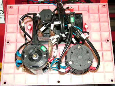
Wiring on the back side of the panel is neatly done, with each wire individually labeled for reference.
Spindle Drive and Quick-Change Gearbox

As mentioned earlier, this version of the C8 lathe uses traditional belt-and-pulley drive powered by a 735 Watt AC induction motor. A toothed belt runs from the motor shaft to the pulley on the left.
For the three higher spindle speeds, the V-belt runs directly between the pulley on the motor shaft to the spindle, or, for the three lower speeds, between the pulley on the left to the spindle. An idler wheel, with sealed ball-bearing races, adjusts the tension of the V-belt.
As on the C6, I replaced the stock nut on the idler adjustment with a T-handle to speed up the process of moving the belt.


Six spindle speeds are available: 150, 250, 500, 800, 1250 and 2300 RPM. This range is sufficient for most work, although I like having a lower speed, such as 50 RPM for jobs such as thread-cutting.
However, for most of the thread cutting I do on the lathe, I decouple the drive belt and use a hand-crank locked into the back end of the spindle. That provides precise control over the thread, and doesn’t take much longer than using motor power – usually less time, since I only have to cut the thread once!
Mounted on a moveable plate, a pair of gears controls the direction of rotation of the lead screw and drive shaft. In the lower position, the carriage moves towards the headstock when the spindle is turning in the forward direction. In the raised position, the carriage moves away from the headstock.
This adjustment can be used for cutting left-hand threads, or for cutting away from the chuck instead of towards it to avoid crashing into a shoulder or other feature on the workpiece. The movement of the power cross-feed also is controlled; in the raised position the cross-slide moves towards the operator.

Power from the spindle is transferred to the Quick-Change Gear Box (QCGB) by a series of gears. The QCGB is a really desirable feature if you frequently cut threads on the lathe. Setting up a gear train manually can take two to five minutes or more, depending on how experienced you are.
With the QCGB you can select any one of fifteen SAE (inch) threads in about 5 seconds simply by moving the two selector knobs to the correct positions. A chart on top of the drive train access door lists the settings for threads from 10 TPI down to 72 TPI.

Update: A while after I published the review, I received from Sieg a package with some additional loose gears. As I had hoped, with these gears installed in the drive train, the C8 cuts a full range of metric threads, including .5, .6, .7, .75, 1, 1.25, 1.5, 1.75, 2, 2.5, 3 and 4 mm.
In its current configuration, this version of the C8, which is intended primarily for cutting SAE threads, has chart positions shown for only three metric thread pitches: .75, 1.35 and 1.50. From the abbreviated manual that I received with this pre-production model of the lathe, it was unclear to me whether more metric threads can be cut with the stock setup. I’ve had some discussion with Sieg about this, and, hopefully, more metric threads will be available on later models.
In addition to thread pitch, the gear box knobs select the power feed speed both for turning and for facing cuts. This feature is discussed in the next section.
One nice feature of this lathe, not found on any of the smaller Sieg lathes, is the separate drive shaft for power feed. On the smaller lathes, the leadscrew does double duty: providing power feed both for turning and for thread cutting. The advantage of having a separate drive shaft is that you can safely take heavier cuts using power feed without risk of overloading the leadscrew.
The power feed shaft moves the carriage by engaging the rack used by the carriage handwheel. A clutch mechanism on the power feed shaft, visible at the left end of the shaft in the photo below, limits the amount of torque applied to the shaft, protecting it if too deep a cut is attempted, or if the movement of the carriage becomes obstructed in some way. (The leadscrew cover has been removed for this photo.)

A pair of small levers is provided to adjust the tension on the clutch spring. Also included is a stop block that spans the front edge of the ways. It can be clamped to the ways to stop the movement of the carriage towards the headstock at a specific point in its travel.
I’m not sure whether this is intended exclusively as a safety guard, or whether it is for general use in stopping the carriage at a specific point, which could be useful for turning to a shoulder, for example.


On the lathe I’m reviewing, I found that the clutch housing, above left, and the leadscrew cover interfere with the carriage moving all the way to the spindle, as when using a faceplate. I passed on this observation to Sieg, so hopefully it will be resolved by the time the C8 starts shipping to vendors.
Carriage and Power Feed
Due to the dual drive options (leadscrew and drive shaft) as well as the power-cross feed capability, the internal structure of the carriage on the C8 is quite a lot more sophisticated than on the mini lathe.


There are three control levers on the carriage:
- Carriage Handwheel
- Half-Nut Lever
- Power Feed Control Lever
Carriage Handwheel
Made from nicely finished cast iron, the carriage handwheel moves the carriage along the ways towards or away from the headstock under manual control.
A long roller handle makes it smooth and easy to rapidly move the carriage, for example, to insert a measuring tool into a hole bored into the end of the workpiece, or to move the carriage near the chuck in preparation for a drilling operation.
Grasping the outer edge of the handwheel with both hands provides good control for making finely controlled cuts, as when touching up the inside corner of a shoulder.

Pulling out on the handwheel disengages it from the gear that it drives so that it will not spin around when the carriage is driven by power feed. The handwheel collar is calibrated in units of .080″ (2 mm) per division or 1.5″ (40 mm) per rotation.
Like the other calibrated collars on the lathe, it can be set to zero at any point in its rotation. While not accurate enough for precision work, the handwheel calibration could be useful for rough turning stock to a specified length.
Half-Nut Lever
The gear ratio selected by the QCGB knobs controls the rotational speed of both the leadscrew and the power feed drive shaft. When the half-nut lever is engaged, the carriage is clamped to the rotating leadscrew and moves at a speed that will cut the selected threads-per-inch (TPI).

When cutting threads, the leadscrew moves the carriage rapidly relative to the spindle speed – especially for coarse threads. Therefore, thread cutting normally is done with the drive belt set at the lowest speed (150 RPM). In fact, I find even that speed can sometimes be uncomfortably fast; when cutting short threads, I often use a hand crank to turn the spindle.
A threading dial on the left side of the carriage can be used to engage the half-nut lever at the proper point so that successive passes over a thread are properly aligned. However, since the spindle is easily reversible, threads may also be cut by leaving the half-nut engaged and reversing the spindle to back out the carriage for the next cutting pass. The choice of procedure is up to you.

Power Feed Lever
The power feed lever controls both longitudinal carriage feed as well as power cross-feed. To select the feed, the black ball is rotated to bring the corresponding symbol into view. The knob is rotated 180 degrees in either direction to change from one feed mode to the other.
A mechanism inside the carriage housing prevents the power feed lever from being engaged while the half-nut lever is engaged and vice versa – an ingenious design.

Labels on opposite sides of the shaft show the direction of feed. When the knob is rotated so that the power feed label (left/right arrows) is facing up, lifting up on the knob engages the power feed. Lowering the handle back to the horizontal, or neutral position, disengages the power feed.

With the handle in the neutral position, rotating it 180 degrees brings the cross-feed label (in/out arrows) into view. Lowering the handle engages the power cross-feed. Raising the handle back to the horizontal position disengages the power cross-feed.

Power feed rates are much slower than threading feed rates. They vary from .0016 to .0115 inches per revolution of the spindle, while cross-feed rates vary from .0008 to .0061 inches per revolution.
The feeds follow a logical progression from A1 through C5, so, if you select a feed that’s too slow or too fast, you can rotate just the A-B-C knob to move to another range. With this wide range of feed speeds, you can find a speed that’s just about right for any operation. And, best of all, it takes only a few seconds to select it and get to work.

I found that much of the noise from the drive train was coming from the tumbler reverse gears meshing too tightly and not being properly lubricated with grease. The C8 runs much quieter now, about 77 dB at ear level when I’m working at the lathe, compared to about 72 dB for the mini lathe running with its lead screw engaged. At that level, ear protection is not needed.
That said, I use the C8 in my shop, located in a spare bedroom of our small retirement home, without bothering my wife, as long as I keep the shop door closed.
Cross-Slide, Compound and Tool Holder

Cross-Slide
Featuring two T-slots along it’s length, the cross-slide forms a solid base for the compound. The compound assembly clamps rigidly to the top of the cross-slide by means of four socket-head cap screws that mate with small T-nuts that slide in the grooves on the cross-slide.

This arrangement allows the compound assembly to be positioned anywhere along the length of the cross-slide. For most work, I mount the compound at the front edge, since that position provides maximum clearance for turning large diameter work.
Although I haven’t tried it yet, I imagine that positioning the compound all the way at the back end of the cross-slide would be handy for operations such as thread cutting on the back side of a workpiece with the spindle running in reverse.
With dimensions of about 4-5/8 x 9-3/8 (120 x 240 mm) and a range of movement of about 6″ (150 mm), the cross-slide serves as a small milling table on lathes equipped with the optional milling head. In that configuration, the T-slots are used to clamp down a workpiece, a small milling vise or other work-holding accessory.
Movement of the cross-slide is controlled by a handwheel with a roller handle. Sharp laser-etched markings on a satin finish background are sharp and easy to read. The collar can be set to zero by holding the handwheel steady while twisting on the knurled ring.

As on many imported machine tools, the collar is calibrated in thousandths of a inch, but the leadscrew is metric. Thus, while the dial is marked as 0.080″ per rotation, the leadscrew actually is 2 mm pitch, which is 0.0787″, a variation of 1.3 thous per rotation. Therefore, the markings should not be relied on for movements of the cross-slide of more than a few thousandths if an exact dimension is required.
The solution is pretty simple: as you approach the final dimension, stop the lathe and measure the workpiece using a micrometer or digital caliper. For movements of just a few thousandths, the variance of the dial markings is pretty much negligible.
Fortunately, the actual movement is less than the indicated movement, so if you forget to compensate, the workpiece will be a little too large, rather than too small, and can therefore be corrected.
Gibs are provided on both the cross-slide and compound slide. In case you’re not familiar with them, gibs are strips of relatively soft metal with a parallelogram-shaped cross-section. The gib fits snugly on one side of a dovetail slide and is adjusted to take up any play.

Five set screws with jam nuts, spaced evenly along the right side of the cross-slide, adjust pressure on the gib. When properly adjusted, the gib ensures that the cross-slide moves smoothly with minimal play and without binding. Over time as the dovetail wears from use, the gib is periodically readjusted for optimum performance.

A socket-head screw on the saddle locks the carriage to keep it from drifting during facing cuts and similar operations. A locking screw also is provided on the cross-slide. It could be useful when doing a turning operation on a workpiece that has openings on its surface, causing an interrupted cut, or when chatter is present.
The vibration in such situations sometimes will cause the carriage to drift in or out, compromising the dimensions of the workpiece and possibly causing the tool to cut too deeply. Another case where it could be handy is when cutting tapers using the compound feed.
Compound
The compound assembly is strong and nicely finished. A steel base over 1/2″ thick (15 mm) locks the compound to the cross-slide by means of four socket-head screws. Ball-spring oil ports provide access for lubricating the leadscrew and dovetails with oil.
Having good clearance above the cross-slide, the compound can be rotated in a full 360° circle. One thing I discovered: if you loosen the locking screws too much, the T-nuts hidden under the compound base can jam, causing the compound to stop at that point. The trick is to loosen the screws just enough so that the compound will turn.
A handwheel calibrated in thousandths (.001″) (.025mm) moves the compound slide. Double handles provide fine control for thread cutting and similar operations. The calibrated ring can be set to zero by twisting the knurled ring while holding the compound handwheel at a fixed position.
As on the cross-slide, the leadscrew is a metric thread, so the calibrations in inches have a small percentage of error. (See comments in cross-slide section). Compensation may be necessary when cutting threads to a standard depth.

Protractor markings from -60 to +60 degrees surround the compound. An index mark on the front of the base is the reference point. The markings are sharp enough that 1/2 degree settings are easily made, as, for example, when setting a 29-1/2° angle for thread cutting, as some machinists like to do.
While sharp and clear, the markings are not as darkly etched as on most other Sieg products that I have used, so they are not quite as easy to read in marginal lighting conditions.

Two socket-head screws in the rotating base lock it in position at the desired working angle. The locking screws are easily accessible, so changing the angle is quick and easy. As on the cross-slide, set screws with jam nuts along the side of the compound adjust the gib to take up any wear that occurs over years of use.

Toolpost
The 4-sided toolpost is the same style that comes standard on the mini lathe, the C4 and the C6, only scaled up to the larger size of the C8. A nicely finished handle provides plenty of leverage to lock the toolpost at the desired angle.
As a matter of comparison, the compound slide on this lathe is larger and heavier than the cross-slide on the mini lathe and, while the mini lathe uses 5/16″ square cutting tools, the C8 uses a full 1/2″ square tool.

As on other Sieg lathes, a spring-detent under the toolpost provides indexed stops for each of the four tool positions. I don’t know if it’s just me, but I like to be able to set the toolpost at whatever angle I judge to be best for the current operation. Usually, that doesn’t correspond to the detent position, so I always remove the detent and spring when setting up the new lathe.
Up to four separate cutting tools can be held in the toolpost at once, letting you rotate the toolpost to bring the desired tool into position. Of course you should move the carriage well clear of the chuck or stop the lathe before making adjustments, and use care not to cut your hand or fingers on the sharp tips of the tools protruding from the toolpost.
Quick Change Tool Post
While the stock toolpost is sturdy and functional, it’s my opinion that a lathe in this class deserves a quick-change toolpost (QCTP). For regular visitors to mini-lathe.com, this is, by now, a familiar refrain; the fact is that a QCTP saves a lot of time while ensuring that the tip of the cutting tool is dead-center on the centerline of the lathe.
This is especially important when making a facing cut. If the tip of the tool is a little high or low relative to the lathe centerline, an annoying little nub is left on the face of the workpiece. With a QCTP, it’s a 10-second job to adjust the tool height to correct this, but without a QCTP, you’re forced to add or remove shims, which can take minutes before you get it right.
I found a suitably sized Aloris-style QCTP at LittleMachineShop.com but when it arrived, I realized that it would not fit on the C8 compound without some modification. The compound has a raised cylindrical area that fits into a mating recess in the bottom of the stock toolpost.

Chris at LMS recommended milling off the raised area, then re-drilling and tapping the compound to accomodate the mounting bolt for the QCTP. After some quick work on the SX4 mill, the job was done, and the QCTP was mounted and ready to go to work.

With some extra toolholders to fit the QCTP, I’m now armed for just about any contingency. The great thing about the QCTP is that swapping to a different tool that’s already mounted in a holder takes just a few seconds.
Even if you have a limited number of tool holders and have to remove one tool from a holder and install a new one, the whole job, including setting the correct height for the new tool, still takes less time than fooling with shims to adjust the height would take. Naturally, the more holders you have, the easier life becomes, so I bought several extras in addition to the five that came with the QCTP set.
The black handle locks the tool holder onto the toolpost. It’s quick and easy to use, but the big nut on top must be loosened and tightened to change the angle of the tool holder relative to the chuck.
That’s an operation that’s done so frequently, that I wanted a dedicated handle, so I made a scaled-up version of the screw cap similar to what I’ve used on the mini lathe, C4 and C6 over the years.

The handle slides through the cylinder so that it can be moved out of the way when necessary and can be used either with a one-hand or a two-hand grip. Once set, it stays where its positioned, even if there’s substantial vibration.

The new QCTP installation works so well that I’m really pleased with it. With some help from Chris at LMS, I passed on to Sieg a recommendation that the compound slide should be configured to easily support Aloris-style QCTPs. So, hopefully we’ll see that as a standard feature going forward.
Tailstock
Well, we’ve worked our way from end of the C8 to the other. Last, but certainly not least, is the tailstock. The tailstock is made from a heavy and nicely finished iron casting. Together with the cast iron block that locks it to the ways, the tailstock assembly weighs over 21 lbs. (9.5 kg).
Here again, the strong structure and heavy weight help to anchor the tailstock rigidly to the ways, enabling more precise drilling and reaming operations. Ball-spring oil ports are provided for lubricating the leadscrew.

To expedite drilling to a specific depth, up to a maximum of 2.5″ (63 mm), both the tailstock quill and the handwheel shaft are calibrated. The quill is graduated both in inches, marked in tenths, and in millimeters.
While these divisions are precise enough for most drilling operations, if greater precision is needed, the tailstock handwheel has a collar graduated in 40 divisions of .002″ (.05 mm), or 0.080″ (2 mm) per rotation.
As on the cross-slide and compound, the graduated collar can be set to zero by holding the handwheel steady and turning the knurled ring on the calibrated sleeve. When turning between centers or to support the right end of a long workpiece, the quill can be locked in place by the lever at the front of the tailstock.

A sturdy lever locks and unlocks the tailstock. If you’ve ever had to lock and unlock a tailstock using a nut and wrench, you’ll appreciate the convenience and time-saving benefit of a lever lock. The lever is long and strong and the locking block is pretty massive; when you tighten the lever, the tailstock is not likely to slip from where you set it.
Twisting the lever a half turn or more unlocks the tailstock and drops the locking block down so that it doesn’t snag on the underside of the ways. When unlocked, the tailstock slides smoothly back and forth on the ways (on the thin film of oil that you’re careful always to maintain on the ways 🙂

A socket-head screw, to prevent the tailstock from accidentally being slid off the end of the ways, normally is in the threaded hole in the bed seen in the photo above.
As on all of the other Sieg lathes that I’ve reviewed, the upper part of the tailstock on the C8 can be offset from the lathe centerline for cutting long tapers. In this type of operation, the workpiece is supported between centers and driven by a dog. Details of this procedure can be found in textbooks on lathe operation or can be seen in this YouTube video.
To offset the tailstock, a locking setscrew on the front of the tailstock is first loosened, then opposing screws on the sides of the tailstock are worked in coordination to move the upper part of the tailstock to the desired offset. Then the locking screw is tightened down.
Conclusion
If you’re looking for a mid-size lathe that you won’t have to mortgage your house to buy, you should consider the C8. Lots of serious home machinists are on the lookout for a nice American-made lathe from the first half of the 20th century.
Unfortunately, those lathes are hard to find, complicated to relocate and can be expensive to maintain if any of the original parts are missing or broken. Plus you may spend a year or more getting the lathe back into good operating condition – if, and that’s a big if, you can find one that’s worth the effort that you’ll need to put into it.
As an alternative, the C8 is pretty much ready to go out of the box. Naturally, you can expect to do some cleanup, adjustment and lubrication, but that’s true of any lathe that you might acquire.
What you get in this case is an accurate and powerful lathe that can do most or all of what you need to do at a price you can afford. Instead of working on the lathe, you can get right to work on your projects. That can be a real advantage if you use the lathe in a money-making operation.
I’m impressed by the quality and features of this lathe. With every new lathe that they introduce, Sieg continues to push the envelope of their capabilities. With its larger size, hardened ways, power cross-feed and quick change gear box, the C8 is in a different class from the C2, C4 and C6 lathes that have preceded it.
Having worked with all of those lathes, I appreciate what they offer – great capabilities at a size and price scaled to the beginning and intermediate home machinist. But I really like the wide-open work area that the C8 provides, as well as the ability to take deeper cuts and use a wide range of power feed speeds to get the job done more quickly – features that should appeal to experienced home machinists and light industrial users.
As is usually the case when I write a review about a new Sieg product, you can’t buy one just yet – at least not in the U.S. After the product has been developed, Sieg’s sales reps travel around the world, visiting customers and attending trade shows to establish sales channels.
Once those deals have been cut, the machines have to be customized and shipped from Shanghai to wherever the dealer is located. All of that takes time, so it will probably be late summer or fall 2013 before you start seeing the C8 being promoted on dealer’s web sites and catalogs.
For now, I don’t have any info on pricing and I don’t want to venture a guess with no facts to back it up. I’ll try to remember to update this page with links when I see the C8 listed. Until then, if you have any questions, feel free to send me an email and I’ll do my best to help you out.
