MacPod Tachometer Kit
On some of their newer model machine tools, such as the SX2 mini mill and SC2 mini lathe, Sieg has included ports for plugging in a tachometer readout accessory.
When not in use, the ports are covered with a rubber cap to keep out chips, oil, etc.
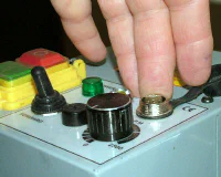 Tach ports on late-model min-mill and mini-lathe
This feature lowers the initial price of the machines for those purchasers who don’t want or need a tach, and gives the purchaser the option to defer the purchase of the tach to a later time when additional funds may be available.
The standard Sieg tach is sold in the U.S. by several retailers including LittleMachineShop.com and Micro-Mark for about $125 at the time of this writing (10/11).
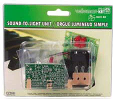
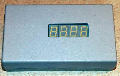
For those who like to tinker with electronics, Macpod now offers a tachometer kit that plugs into the port on the SX2 or SC2. Unlike the standard tach, which uses a blue backlit LCD display, the Macpod version uses bright LED digits in your choice of red, green or blue. Macpod also sells pre-assembled boards.
You’ll still need to make a case for the display, but that requires no electronics assembly skills.
Back in the 1970’s I enjoyed making a number of Heathkit electronic kits including an oscilloscope, VTVM voltmeter, HW-101 amateur radio transceiver, a shortwave receiver and a flatbed plotter.
Heathkits were a pleasant way to spend a cold, rainy winter day, while learning electronics theory and practical wiring and soldering skills. When you were all done, you had a useful product and the pride of having made it yourself. So I was intrigued when Macpod sent me one of their tach kits to review.
It sat on the shelf for a few months while I was busy with the typical summer activities, but today, being cold and rainy, seemed like a good day to work on the kit.
With only about 20 parts and a clean design with all components mounted on a printed circuit board (PCB), this kit should be easy to complete for anyone with basic soldering skills. No special knowledge of electronics is required.
If you’ve never soldered PCB circuits before, you can still tackle this kit - just be sure to practice your soldering skills on some scrap materials first.
You can find some tutorial resources on the internet to help you get started - or you can buy the kit pre-assembled.
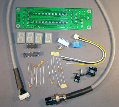 All of the components - not too bad!
To build the kit, you’ll need few basic electronics tools, including the following:
- Low wattage (20-45 watt) soldering iron with a fine tip
- Rosin-core solder intended for electronics (not plumbing solder)
- Damp sponge or other soldering-tip cleaning tool
- Small diagonal cutters to trim component leads
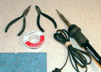 Tools needed for soldering the PCB
Also handy, but not essential, are a pair of small needle-nose pliers and a small vise for holding the PCB.
You can get all of the tools you need at Radio Shack, including some inexpensive kits that would be good for practicing soldering before tackling the tach - the one shown below is about $8 as of 10/11.
 Radio Shack kit for practicing soldering
Assembling the Circuit Board
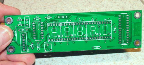 High-quality printed circuit board
Assembling the tach board is really pretty simple: Just insert the leads for each part into the top side of the board, using the silk-screened component outlines and numbers as a guide, then solder the leads to the backside and clip off any excess length from the lead wires where necessary.
Detailed assembly instructions are provided on the Macpod web site. Some components, such as the LED digital readouts and the integrated circuit chips, must be installed in a particular orientation - so pay close attention to the instructions.
Other components, such as capacitors and resistors can be installed without regard to which lead goes into which of the two holes marked for that component.
For soldering, the technique I like to use is to hold a short length of solder in a “third-hand” clamp and bring the board and the tip of the soldering iron to the solder. Often, I tack down just one of the leads for each component, saving the rest to be done all at once.
If you’re new to this, a “third-hand” is just a clamping device of some sort to hold the board, a component, solder, etc. while soldering - since it often takes more than just two hands to get the job done. You can buy them inexpensively on the internet or at Radio Shack, or you can make your own if you’re so inclined.
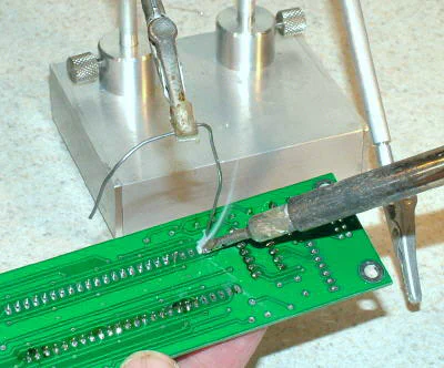 Using a “third hand” to hold a length of solder
When necessary, I use a finger to hold the component in place until the first lead is soldered to hold it down. Make sure when soldering the LED displays to the board, that they are seated firmly.
I failed to do that with one of them, resulting in a slightly canted mount. Once the solder sets, realigning a part can be difficult, especially for parts like the LEDs that have multiple pins soldered to the PCB.
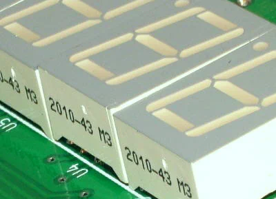 Slightly tilted LED display
After many years of using a crude third-hand that I made back in the 70’s, last year I made a much nicer one. It has stick-on rubber feet on the bottom and some lead weights in the base to keep it from moving around.
This is what you get when you have a lathe, a mill and too much spare time.
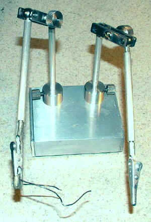
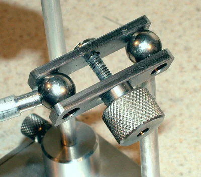
Shop-made third-hand with weighted base and interchangeable holders. Double ball joints enable flexible positioning of the arms. The arms can be removed to store the device in a shallow drawer.
Once I have the components tacked down, I hold the board in an electronics vise, or using both clips of the third-hand, and solder all of the remaining pads.
This is a quick and efficient way to get the job done.
 Holding the board using the third-hand
Beware of solder bridges - where the molten solder flows across two adjacent terminals that are not intended to be connected together.
 A solder bridge between two adjacent terminals
If you get one, reheat the solder, and while it is still liquid, use the tip of a sharp steel scriber or a special aluminum probe, made for just this sort of situation, to break the unwanted bridge.
When you have finished installing all of the components, (and before plugging it in to the lathe or mill!) check the board carefully to make sure you haven’t missed any connections or for any solder bridges or splashes that might cause a short circuit.
Note: the small droplets that look like water actually are solder flux. Solder for electronics work has a flux core that melts and enhances the flow of the metal solder.
It is non-conducting, so it can be left on the board without concern. Solder manufactured before the 1990’s had a high lead content and a type of flux that leaves a reddish-brown residue.
I still have and use solder from that era, so you may notice some of the brown resin residue on the photos of my board.
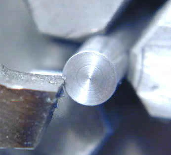
An aluminum or sharp steel probe is handy for breaking up solder bridges. Molten solder will not stick to aluminum and usually will flow away from a sharply pointed steel tip.
 Molten solder will flow away from a sharp steel tip
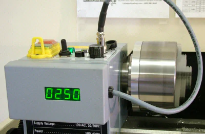
After all of the components have been soldered to the board, and the board has been checked to be sure it’s free from solder bridges, balls or splashes, it’s time to test the readout.
Follow the Testing instructions on the Macpod web site and you’ll soon see the tach displaying the running RPMs of the machine.
Don’t be surprised if the tach readout periodically changes by 10 or 20 RPM - that’s a normal variation for any type of digital tachometer as it averages the RPMs over a sampled time interval.
Also, especially while under load, the motor speed may vary by even more than that.
Mounting the Tach in a Case
One component not included with the kit is a case. I’ve been an electronics experimenter since the early 60’s, so I had a few plastic project boxes laying around, including one that was a reasonably good fit (5.6 x 3.2 x 1.5") for the tach PCB.
Similar boxes can be bought from Jameco or other electronics distributors.
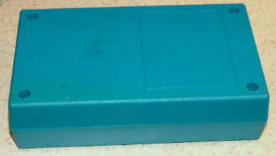 A typical electronics project box
I needed some standoffs (threaded spacers to raise the PCB above the bottom of the case) to bring the surface of the LED readouts close to the front face of the case.
I had quite a few lying around from various electronic equipment that I had salvaged over the years, but what I needed was spacers about .90 inches in height.
The ones I had on hand were 1/2" or 3/4" high, so I decided to make some new ones on the lathe from 5/16" diameter aluminum rod. I cut off four pieces about a little over 1" long.
I faced each piece to bring it to a length of .90", then drilled and tapped one end of each piece 6-32.
I attached each spacer to the pre-drilled mounting holes on the PCB using a 6-32 x 1/4" pan-head screw and then determined how I wanted the PCB positioned within the case.
I then placed the PCB on the workbench face down, with the ends of the spacers sticking up, and placed a small dab of JB-Quick epoxy on the end of each spacer.
Finally, I repositioned the PCB in the case so that the ends of the spacers with the epoxy adhered to the back of the inside of the case. The PCB ensures that the positioning of the spacers will be correct once the epoxy solidifies.
I later found that the epoxy did not adhere well to the shiny inside surface of the case. Therefore, I recommend roughing up the surface where the standoffs will go to give the epoxy a better grip.
I made a series of cross-hatched grooves using a small snap-blade knife.
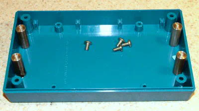 Standoffs epoxied to case
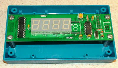 PCB mounted on standoffs
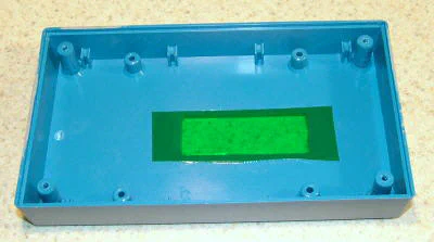
The next task was to cut out a rectangular window for the LED display. I positioned the case on my surface plate and used the height gage to measure the offset to each of the four edges of the displays.
Because the edges of the case are angled, I pressed the back of the case up against a 2-3-4 block so that the case would be vertical when taking the measurements.
After setting the tip of the height gage to the edge of the displays, I locked the height gage and then placed the front half of the case on the surface plate and used the edge of the tip to scribe a line on the face of the case.
I repeated this for each of the four edges of the displays so that I had a rectangle marked for the cutout.
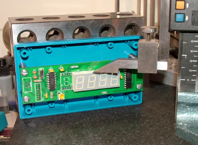 Setting the height to the top edge of the LED display
 Transferring the measurement to the front panel
Now, with a rectangle marked, it’s a simple matter to mill out the window. I used a 1/8" dia. 2-flute end mill and plunged into the work to begin the cut.
Make sure that the case is square to the table when clamping it down. Clamp over the edges for best rigidity - but not too tightly or you could crack the plastic.
 Cut along dotted line…
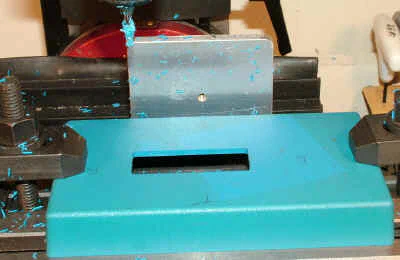
In the photos above, you may notice on the box a shadowy outline of a blue square. That’s a result of this box sitting around for years with another box on top of it.
Over time, sunlight and/or fluorescent lights caused the case to turn color, except where it was shielded - kind of like a photographic negative. Not to worry, I’m going to paint the case.
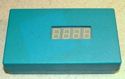
Later that day…
 Case painted with gray spray paint
Next, we need to route the cable from the PCB out through the side or back of the case. Due to the relative stiffness of the cable, it seemed to me that the best option was to go out through the right side of the case.
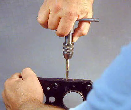
After marking the hole location using the height gage, I drilled it out on the mini mill.
I used blocks of scrap aluminum on either side to help keep the plastic box from flexing. This setup didn’t leave enough clearance for regular drills, so I used a step-drill and a slow spindle speed. I got a pair of these step drills from Harbor Freight for about 15 bucks.
They’re great for situations like this where you need to drill a fairly large hole in thin material and the hole does not to be a precise diameter.
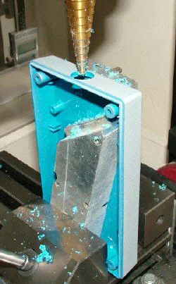 Drilling the cable exit hole on the mini mill
One minor problem I ran into: after drilling the cable hole I found that both ends of the cable, due to the connectors, are too large to fit through the hole.
In my case, this was easily solved simply by using wire cutters to clip away the edge of the hole near the centerline of the case, but it might be a more complicated problem if your mounting hole is located somewhere in the middle of the case wall.
(Update: Later, after pondering this some more, I found that I could get the linear connector to fit through the hole by turning it sideways (parallel to the cable)).
After adjusting the cable position so that it was just the right length to reach the exit hole, I snapped it into the provided strain relief and pressed the strain relief into the hole.
The last step of the case construction is to make a transparent green window for the green LED display. The window helps to hide the face of the LED displays, so that only the glowing digits are visible, and also helps to improve the contrast of the display for better visibility.
So, where do you find transparent green plastic on a Sunday morning? A quick trip to the Dollar Store about two miles up the road was in order.
Shopping can get interesting when you don’t need a particular item, but any item that meets particular characteristics - in this case, made of flat, transparent, green plastic.
Before long I found an ornamental bowl that looked promising. I paid $1.00 for it, plus $.05 for the governor, and was on my way back to the shop.
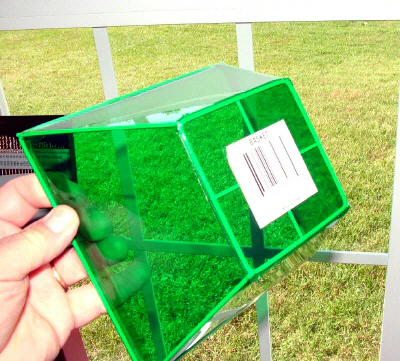 A transparent green decorative bowl is just what I need!
Some quick work with a snap-blade knife and some scissors and I had a rectangle of plastic for the window. I glued in place with a thin bead of super-glue.
Now, on to mounting the tach on the lathe.
 Window glued in place
Usually I’m not a big fan of using Velcro or double-sided tape for mounting things.
I like the permanence of screws. But in this case, a Velcro-type tape made a lot of sense since it would let me quickly and easily move the tach between the mini lathe and mini mill, or remove it all together if was not needed or was in the way of some special maneuver.
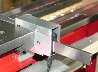
 Stick-on Velcro strips hold the case in place
As soon as I held the tach up to the lathe it was obvious that I should have run the cable out the left side of the case rather than the right side.
That would make internal routing of the cable less convenient, but would put the cable in a much better (and safer!) position on the lathe.
Well, at least the case fits nicely on the front of the lathe.
 Hmmm… this doesn’t look good!
Drilled a new hole in the left side and did a quick re-route of the cable …
 That looks much better - and safer!
I used an existing screw on the lathe to install a small nylon cable clip to secure the loose length of cable. The clip is open-sided so that the cable can be detached without removing the clip.
Conclusion
As I had expected, I had fun making this kit. It brought back some good memories of the old Heathkit days. Ah, the smell of fresh solder smoke on a cold day!
The tach board is well-designed and all of the components are top quality. If you follow the instructions and do a good job of soldering, you can have the board completed in about an hour - maybe less if you’re an experienced PCB board builder.
Mine worked the first time I plugged it in. I checked it against my Sieg-made tach and both gave identical readings (including the occasional shifting of the readout) over a wide range of speeds that I checked on both the mini-lathe and mini-mill.
Making the case and installing the board in it actually took longer than wiring the components to the board.
Because I was taking a lot of photos along the way, I didn’t get an accurate measure of how long it took me to complete the case, but I’d guess about two hours had I not been doing the photography. (Not counting the trip to the Dollar Store.)
Other than that little detour of re-routing the cable to the left side of the case, the project went smoothly.
Gives me an idea for a new slogan: “mini-lathe.com - we make the mistakes first, so that you don’t have to!”