7x14 Mini Lathe
A new lathe was dropped off at mini-lathe.com by the UPS truck a few weeks back.
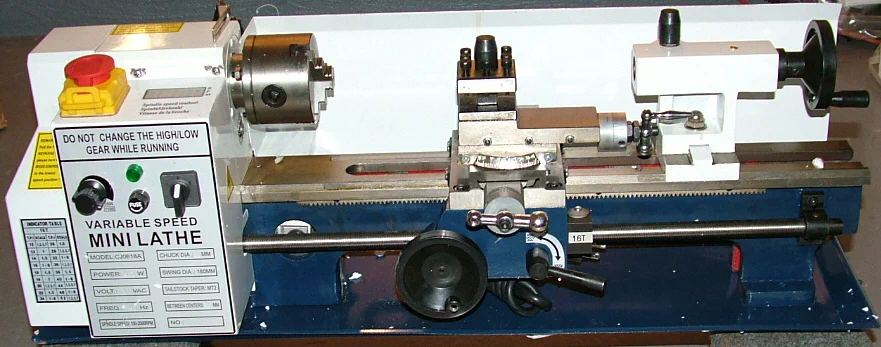
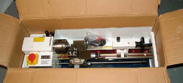
7x14 Mini Lathe from Big Dog Metal Works - fresh out of the box with styrofoam chips still in place…
Some points of interest…
- A true 7x14 (2" longer than the 7x12)
- Blue and white paint scheme
- Built-in digital tachometer (next to Emergency Stop button)
At first glance, it may remind you of the Micro-Mark 7x14 - but on closer comparison, you’ll see that they are two different machines.
Long-time readers of mini-lathe.com may recognize some features that this lathe has in common with the “old-style” Homier 7x12 lathe. Available only for a limited time, that lathe was very well liked by owners who purchased them.
I never did learn who the manufacturer was, or where they are located, but it’s good to see it available once again, this time in a new improved format, and from a new US distributor.
I did some more research, and received a helpful tip from a reader. Near as I can tell, this lathe is manufactured in China by Yangzhou Real Bull Machinery, Ltd.
The lathe was provided by Big Dog Metal Works (BDMW), a business venture formed by five guys in Oregon.
Bound together by a common interest in flying, they reached that stage in life where it was time to try something new, and so BDMW was launched, originally using eBay as a store front for their operations.
One of the most cool things about the internet is that you can start a business with national, or even global reach, without investing in a brick and mortar building.
Web sites such as eBay and Amazon provide the business with off-the-shelf tools for showcasing products, transacting sales and expediting shipment. Update: Now, in 2011, with a few years of operating experience, Big Dog has moved from eBay to their own online store.
Each of the five partners brings a unique set of skills to the venture - such as accounting, computer sales, auto repair, telecomm, etc. - providing a rich base of experience and insight necessary to run a business.
Impressed by the quality of this 7x14 lathe, they chose it as their first product. They’ve invested a considerable chunk of money into this venture, with plans for growth and expansion into additional machine tool offerings, so keep an eye on their online store.
Shipping and Receiving
It’s a long way by boat from China to the U.S.
If you think about all the transfers - factory to truck, truck to warehouse, warehouse to truck, truck to dock, dock to boat, boat to shore, boat to dock, dock to truck, truck to warehouse.
.. well, you see what I mean. It’s amazing that any goods make it intact. So when I opened the box, I was prepared for bad news. But, as has been my experience with other machines shipped from China, a few bumps and bruises are standard, but the important stuff usually arrives in good shape.

Getting the lathe from box to bench took a little work. Some sweat equity was involved, even in January, when sweat is harder to generate. Oh, and I used the shop crane.
At 42KG (~93 lbs.) net weight, I would be asking for trouble if I tried to heft this thing up onto the bench without the help of the crane. I don’t have any neighbors or nearby friends who share my enthusiasm for machine tools, and my wife, though she deeply loves me, has grown weary of being pressed into service as a day laborer.
The crane, together with a 2" wide nylon strap attached to the lathe bed, also makes it easier to get the lathe out of the box, since it’s tricky to get a solid grip on it to lift it out by hand, even if you’re young and strong.
After the usual cleanup and fine tuning, the lathe was looking good - and ready for evaluation and testing. One thing that sets this brand of lathe apart from the Sieg-made lathes: the packing grease is relatively light.
That makes initial cleanup easier, but I did find a few areas where minor rust had worked its evil deeds. Rust, as we all know too well, never sleeps - and especially not on a transoceanic voyage in company with finely machined steel.
General Construction
Like all the mini-lathes, this one is built around a solid cast iron bed, but in this case, the bed is a full 22" long from the headstock to the end. The bed and sheet metal components are painted a dark royal blue color, with a red “racing stripe” down the length of the ways.
Down inside the bed, red paint protects the casting from rust. The headstock and tailstock are a clean white color, which, set off by the dark blue bed and sheet metal, plus the red accents, make a nice-looking lathe.
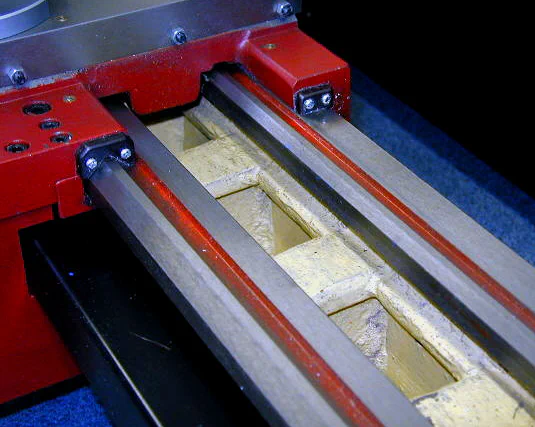 Bed casting and precision-ground ways
On the end of the bed, a label reads “HEAT TREATMENT” - just as on the old-style Homier 7x12. Presumably this means that the ways have been hardened to some degree, or perhaps that the bed casting has been reheated after casting to relieve stresses left in the metal during the casting process.
Here’s what it says in the user manual:
> The lathe bed is made of high grade iron. The rigidity of lathe, the hardness and accuracy of the v-slideways are obtained by raw materials, heat hardening and grinding.
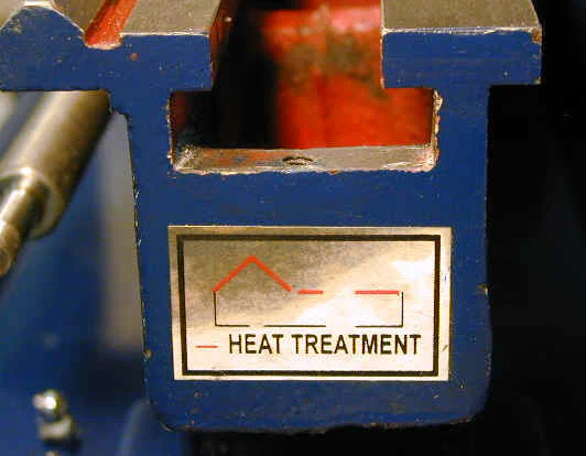 Heat treatment label (slightly stained by oil)
It’s good practice to remove the carriage and compound, strip them down and clean them thoroughly in kerosene or WD40 (liquid, not spray). Doing so removes all of the packing grease and grit that’s an inevitable side effect of the manufacturing and shipping process.
Additionally, if you’re new to mini-lathes, the cleanup process is a great way to familiarize yourself with all the parts and how they work together - knowledge that will almost certainly come in handy later on in your lathe adventures.
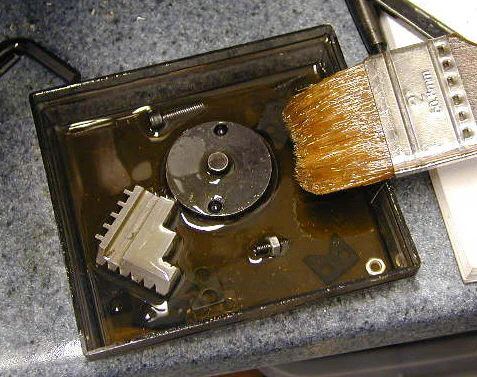 Cleaning up small parts in kerosene
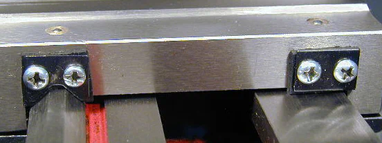
To remove the cross-slide, you’ll first need to remove the chip guard. This is no big deal - just remove the four screws on the back side of the lathe and the single screw behind the chuck.
Replacing it, though, can be a big deal. Due to the location of the screws, you have to jiggle the chip guard with one hand, to line up the screw holes, while trying to get the screw started with the other hand.
Of course the screw, aggravatingly, drops down into some recess under the bed.
So, I will now reveal another of my highly coveted, prized and protected trade secrets: run down to the local Radio Shack, computer store, or online equivalent, and get yourself a screw-starter.
These handy little gizmos have three spring-steel prongs that expand and then retract to hold a small screw in place while starting it into a hard-to-reach screw hole.
It takes a little practice to use them, but once you get the hang of it, they can be a great time and frustration saver.
 A screw-starter can be a big help
Here’s another tip that’s saved me a few times: take some digital photos of each assembly before you take it apart. Then, later, if you can’t remember how things went together, you can refer back to the photos - displayed large-size on a PC monitor.
As has happened on just about every mini-lathe I’ve received over the years, the sheet metal chip tray got a few minor bends and dings on the way here from the factory.
A few minutes with a pair of pliers, with a piece of thin rubber between the jaws to keep from scraping the paint, got things back into reasonable shape.
In any case, it has been my practice to remove the chip tray and mount my mini-lathes on a piece of 3/4" thick MDF - with holes drilled in it to match the rubber feet on the lathe.
This arrangement prevents small parts and tools from getting lost underneath the chip tray, which they inevitably do.
Electronic Controls and Motor
A nice feature on this lathe not found on most of the other mini-lathes is the integral digital tachometer. While precise control of the spindle RPMs is not really essential for the type of work you’ll do on a lathe in this class, the tach can be especially helpful to those new to the craft.
It helps them to get a feel for what speeds work best for various materials under different working conditions.
Also, while not really necessary for hobby work, those who like to do things “by the book” can look up recommended cutting speeds in a reference manual and set the RPMs for the optimum cutting speed.
Without a tach, there’s really no easy way to know how fast the spindle is turning. Last, but not not least, it looks cool - always an important factor for impressing visitors to your shop!
OK, let me just say it. It’s damned hard to get a good photo of a LED display (well, for me it is!). Technorati know that digital displays are multiplexed.
While they appear to the human eye as a steady continuous display, they are in fact, time-shared (like tiny ocean-front condos) flickering at a rate that the eye-brain collaboration blends into a steady image.
Anyway, the camera does not do a good job of capturing how they really look. Too much external light and they look washed-out; reduce the light and they look blurred, as below.
In actual use they are steady and bright.
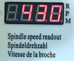 LED readout on digital tachometer
Noting the legend below the tach, I thought it interesting that what takes four words to say in French takes only three in English - and only one in German.
To the left of the digital tach, is the ON-OFF and emergency cutoff switch. It has a hinged lid, with a big red emergency STOP button. Underneath the lid are green ON and red OFF buttons, protected from oil, grease and chips by a flexible rubber-like membrane.
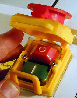 Power ON-OFF switch
When the lathe is in use, the lid is left open, but resting just above the buttons. The green and red buttons are used turn power to the lathe on and off.
On the outside of the switch cover, the big red button is mechanically coupled to the red Off button underneath the cover. Should an emergency situation develop, you can quickly stop the lathe by mashing down the big red button with the heel of your hand.
This causes the red Off button underneath to be depressed, shutting down the lathe. When the lathe is not in use, a small padlock can lock the switch cover shut so that the lathe cannot be started by curious shop visitors.
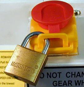 Power switch cover secured by a padlock
Mounted on the front of the electronics enclosure we find the following items
- Speed control knob
- Pilot light
- Fuse Holder
- Motor direction selector
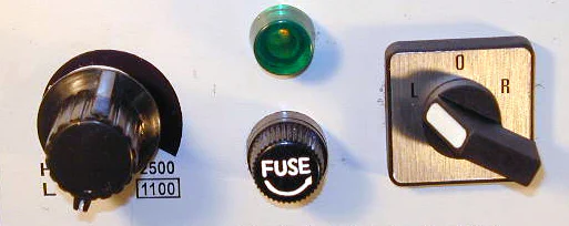
To operate the lathe, the motor direction selector is normally left in the L position, which causes the spindle to rotate in the counterclockwise direction.
Integral to the speed control knob is a switch that resets the lathe when the speed control is turned all the way counterclockwise. In normal operation, the lathe is started and stopped using the speed control knob, starting in the fully counterclockwise position and rotating it clockwise until the desired speed is reached.
To stop the lathe, the speed control knob is rotated counterclockwise until the switch can be felt and heard to click off.
Before you start the lathe, you must first reset the RPM control dial to zero. Not only does this avoid a potentially dangerous condition that could exist if the lathe suddenly accelerated to high speed, it has been my experience that is places less load on the electronic speed control, making it less likely to blow a fuse (or worse, a MOSFET) while accelerating the chuck up to speed - especially when using a more massive 4" or 5" chuck.
MOSFETS are specialized power control transistors used in the speed control and, on the mini-lathes made prior to around 2004, had a tendency to get fried.
That was at least partly because the controllers in those days did not require reset to zero before starting. So, I’m happy to report that, not only are these new lathes safer, they’re also more reliable.
Controlling the lathe in this way has at least two advantages. The speed is increased gradually under direct control from the operator. If any unexpected conditions arise, the operator can immediately stop the lathe.
Secondly, it is my belief that starting and stopping the lathe gradually in this way reduces stress on the speed control electronics, making them less likely to fail.
Early versions of the mini-lathe, lacking this gradual start/stop feature, often had failures of the speed control electronics.
The motor direction selector is most often remains in the L position. The R position rotates the motor in the clockwise direction, as for cutting right-hand threads.
Clockwise rotation is sometimes also used for special cutting operations from the backside of the workpiece, but I won’t get into that here. In fact, although I’ve read about it, I’ve never actually had any reason to try it.
I’ve rarely found any need to operate my lathes in the clockwise direction.
Around the backside of the lathe, I removed the motor cover to take a look under the hood. This process was a little more more complicated than I’ve been used to on my older mini-lathes, because the newer ones now include an electrical interlock switch to prevent starting the lathe with the chuck key left in the chuck.
On this lathe, the switch is mounted on the back of the headstock, and a protective cable channel runs down the back of the lathe into the motor area.
After a few minutes work I had the motor cover off.
 Motor cover on back side of lathe
The brush-type DC motor is a larger than the ones in my older 7x12 lathes, which are rated at about 400 watts. I didn’t see any rating plate on the motor - maybe there’s one on the other side, but I didn’t want to remove the motor to find out.
On their eBay store, Big Dog lists it at 550 Watts, or about 3/4 HP. Although I’ve never had to replace a motor brush on my old 2000 vintage mini-lathe, it was good to see that access ports to the motor brushes are provided, just in case you need to change a brush.
By the way, if you’ve never seen one, the brushes are made from a compressed carbon compound and look like a 1/4"-square pencil lead.
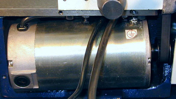 3/4HP drive motor
Over the years, the motor control electronics on the mini-lathes have gotten increasingly sophisticated - and better made. On this lathe, the speed control circuit board uses tiny surface-mount technology (SMT) electronic components installed under robotic control.
The result is a much cleaner and smaller board, and no doubt more reliable, than could be constructed by hand. A second board, mounted in the bottom of the electronics enclosure appears to be the DC power supply.
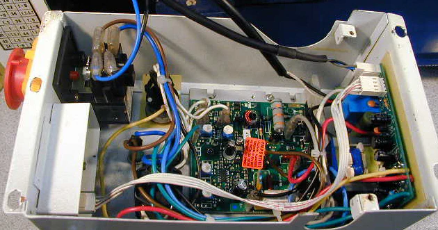 Inside the electronics housing
All of the mini-lathes use some form of pulse-width-modulation to control the motor speed. This technique uses a DC motor, at about 100 volts, to which the input power is electronically sliced.
The result is accurate and steady speed control combined with high torque. High torque is especially important when operating the lathe at low RPMs - more about that later.
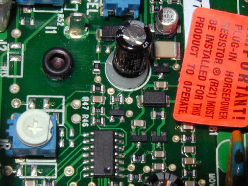 Circuit board with SMT components.
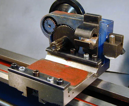
Headstock and Change Gears
The headstock is built on a heavy casting that encloses the spindle, the spindle speed range selection gears and the bearings that support the spindle.
Extending out the left side of the headstock casting, the tail end of the spindle engages with the drive belt from the motor and the gear train that drives the leadscrew for power feed and thread cutting.
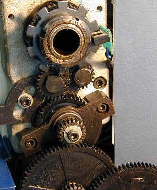 Spindle (at top) engaged with gear train
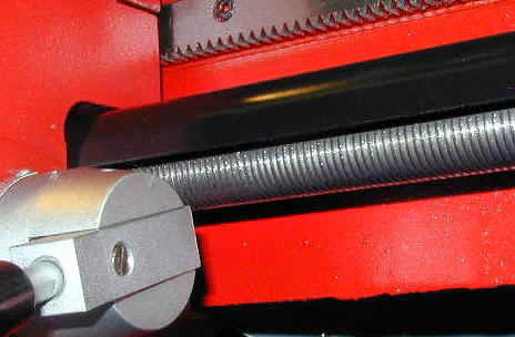
An adjustable take-up nut on the right end of the lead screw allows you to compensate for any lateral play.
On the left side of the lathe is the cover for the change gear train, along with a table of gear selections for cutting a wide range of inch threads from 12 to 52 threads per inch (TPI).
In fact, as Varmint Al pointed out years ago, you can also cut a wide range of metric threads, at least to a very good approximation. Paul Bussieres later created a very nice Visual Basic program (follow link to Varmint Al’s page) that will calculate the gear setup for just about any thread pitch you’re likely to need.
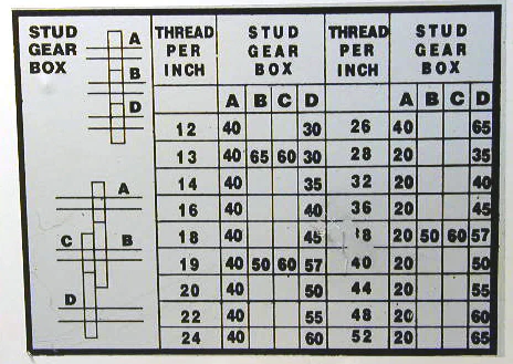 Gear selection chart for inch thread pitches
The gear train sets up the lathe for cutting threads of a desired pitch or for power feed. When using the power feed, the lowest gear ratio is selected using the two 80-tooth gears.
For cutting threads, the desired pitch, in threads per inch (TPI) is looked up on the table affixed to to the gear cover. From the table, the appropriate gears are selected and mounted to drive the leadscrew.
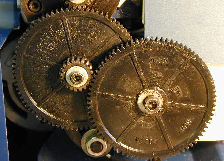 Gear train with two 80-tooth gears for power feed
A threading dial indicates the proper point at which to engage the half-nuts when cutting threads.
 Threading dial
Standard on all of the mini-lathes is a HI-LO gear selector lever mounted on the back of the headstock. For nearly all work, except for the occasional polishing job, or perhaps some work on very small diameter stock, the lathe is used in the LO range.
The approximate speed ranges are
- LO 30-1000 RPM
- HI 200-2400 RPM
The sensor for the tach reads the actual spindle speed, so it is accurate in both ranges.
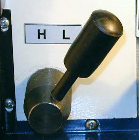 HI - LO speed selector lever on back of headstock
One thing I’m always curious about when I test a new lathe: what’s the lowest practical RPM at which it will run, and how much torque is available at that low speed.
For operations such as tapping and threading, low speeds are what you want. Too much speed - even 100 RPM - makes it tough to control the operation, resulting in broken taps or threading tools and ruined work.
Therefore, I was very impressed to find that this lathe has strong torque right down to around 30 RPM - a great feature. As load is applied that works to slow down the spindle, the electronic speed control compensates with additional power to maintain the selected RPM setting.
Very nice.
Spindle & Chuck
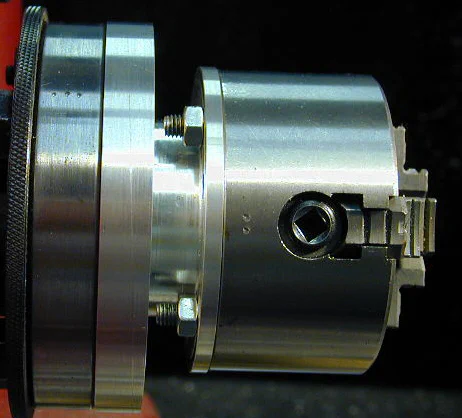
Nicely finished to a bright sheen, the hardened steel spindle has the standard layout of six holes for direct mounting of 3-jaw and 4-jaw 3" chucks. As on the 7x10 and 7x12 lathes, the spindle diameter, and standard chuck diameter for this lathe is 3".
With appropriate back plates, it will also accept optional four- and five-inch diameter chucks.
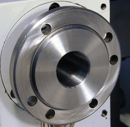 3" diameter spindle plate
The center hole of the spindle accepts #3 Morse taper accessories, while providing a through-hole of just over 3/4" (0.750"). When facing, drilling or tapping the end of a long workpiece, the end of the workpiece can extend through the spindle and out the left side of the machine.
However, the through-hole in the chuck is only 5/16" (0.625") so, to take full advantage of this feature, you’ll need a 4" 3-jaw or 4-jaw chuck - something you’ll soon want in any case, for it’s larger work-holding capacity.
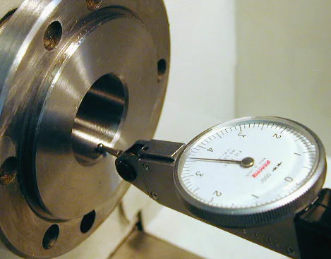 Measuring runout with a dial-test indicator
Using a dial test indicator, accurate to one-ten-thousandth of an inch (.0001"), I measured the runout at the spindle bore at 4 tenths - 0.0004", very good for a low-cost hobbyist-class lathe. In essence, runout is a measure of any “wobble” of the spindle and bearings supporting it.
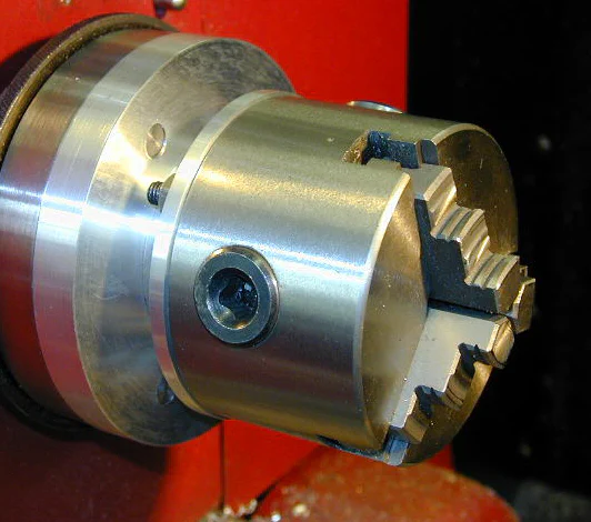
The chuck is a standard 3-inch, 3-jaw; a practical workhorse for this size lathe, and a good size for beginners since it is safer than larger chucks that have more mass and are more likely to strike an unintended object.
It goes without saying, that great care is in order any time you are working close to a spinning chuck. That starts with ensuring that your workpiece is tightly clamped in the jaws - not skewed to one side.
 Standard 3-inch, 3-jaw chuck
Failure to observe this rule one day when I was in high-school shop class (back in the 60’s), led to my launching a 3 lb. piece of steel out the shop window.
I was doubly lucky that day: no one was injured and, miraculously, no glass was broken! (nor were any animals harmed).
The workpiece flew through the open window without breaking it, landing on the grass outside. (Nope. No air conditioning.) While my fellow shop classmates found this whole episode hilarious, my shop instructor did not.
Discipline was not taken lightly back in those days, and so it was that I was assigned 25 pushups a day at the start of shop class, to atone for my carelessness. After two weeks, I was looking buff. And I still remember that lesson.
Of all the projectiles launched by metal lathes, chuck keys may be the most common. Since at least the 1940’s when chucks came into common use, until just a few years ago, chuck keys have been essentially unchanged.
Fortunately, lathes manufactured in the last 4-5 years now come standard with both a chuck safety interlock as well as a spring-ejector on the chuck key itself.
Bright red handles also serve as a visual cue when the chuck key is in use.
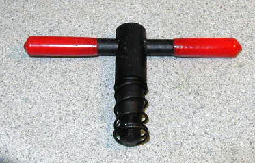 Chuck key with ejector spring
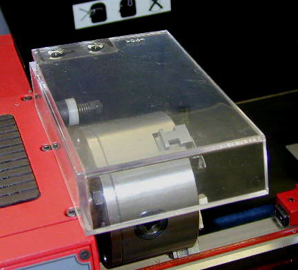
On this lathe, a heavy-duty plastic shield must be lowered into place in order to start the lathe. A switch attached to the hinge engages an electrical interlock that prevents the lathe from starting when the shield is raised - as it must be to engage the chuck key with the chuck.
Integral to the chuck key is a spring that ejects the key from the chuck if hand pressure is released - thus making it close to impossible to leave the key in the chuck unintentionally, lurking there, later to become a projectile when the lathe is powered up.
 Chuck interlock cover
But back to diligence for a moment. Even with all the improvements that have been made, the accident that I described from my high school years still would only have been prevented by carefully ensuring that the workpiece was securely held in the chuck before starting the lathe.
The lesson here is: don’t depend on technology to keep you out of trouble; it can help, but you need to do your part.
Carriage & Cross-Slide
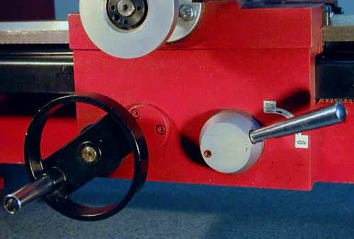
The front part of the carriage, or apron, is cast iron in construction. Mounted on it are the the carriage handwheel, for moving the carriage back and forth along the ways, the half-nut lever, for engaging and disengaging the leadscrew during power feed or threading operations, and, on the right side, the threading dial, which indicates the point at which to engage the leadscrew for thread cutting.
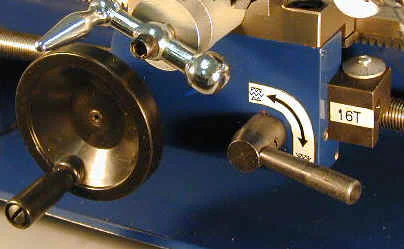 Carriage handwheel, halfnut lever, threading dial
I found that the carriage handwheel had a smooth and positive feel while moving the carriage, and that the half-nut lever also had a good feel - almost as if it had a ball detent to snap into place at either end of its travel.
These may seem like minor considerations, but the “feel” of a machine tool actually does have an effect, good or bad, on the quality of work that you can produce on it.
 Underside of carriage assembly
The horizontal part of the carriage is also cast iron, but is machined on all sides to a smooth finish. Flexible rubber way-wipers on each side help to keep a smooth film of oil from the oil ports spread on the bearing surfaces of the ways, and to keep metal chips and other debris from becoming lodged under the carriage.
 Oil ports and way-wipers
With the cross-slide removed, you can see the finely finished surfaces on which the cross-slide rides. This high-quality finish ensures a smooth movement of the cross-slide, with little slop, to help ensure a fine finish on the workpiece.
 Carriage with cross-slide removed
When I removed the cross-slide for cleanup and lubrication, I found a small amount of rust on the underside. This suggests that the manufacturer needs to be a little more thorough in protecting these hidden surfaces with shipping grease.
A little work with an SOS pad and some water in the sink and it was soon looking pretty good. Water? Sure, as long as you are careful to rinse off all of the soap, dry the part carefully - being sure to remove any water droplets from the recesses - then treat the bare metal with a fine layer of oil, water is fine.
There may be others out there who disagree, but I’ve been using this cleanup technique for years with good results.
 Cross-slide before cleanup
 Cross-slide after cleanup
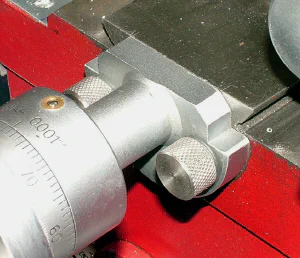
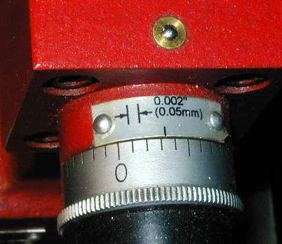
The cross-slide handwheel is long and smoothly tapered. Sharply-etched markings and numerals make it easy to accurately gauge progress as you advance the tool into your workpiece.
The scale is locked into place by a set-screw that can be loosened to zero the calibrated dial.
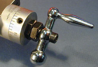
By grasping it between thumb and forefinger just beyond the thickest part, you can turn it rapidly to advance or retract the cross-slide with little tendency to bang your knuckles on the cap screw that holds the handwheel in place.
Where more precise control is needed, you grasp both ends of the handwheel and turn as slowly as needed.
 Use thumb and forefinger when precise control is called for
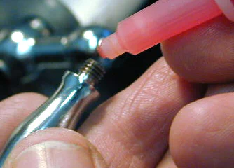 A drop of Loctite will keep the handles from unscrewing
On the dial, the legend indicates that the divisions are 0.025mm or 0.001". In fact, as on all of the mini-lathes except for the Micro-Mark 7x14, the lead screws use a metric thread.
Therefore, the divisions are not quite exact for inch measurements, but are close enough for all practical work as long as you measure your work with a dial caliper or micrometer as you approach the final desired diameter for your workpiece.
Over a span of one rotation of the handwheel, the error is small enough to ignore for all but the most precise work.
Compound & Toolpost
The compound, also know as the compound rest, rides atop the cross-slide and can be rotated for threading, cutting shallow tapers or just according to personal preference.
Like the cross-slide, it has an adjustable dovetail slide to keep it tight enough for accurate work, while allowing for adjustment for wear over time.
Three adjusting screws with locking nuts on the side of the compound slide are used to tighten or loosen the gib as needed. A silver-finished plastic protractor helps in setting the compound to a specific angle.
 Compound
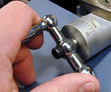
Similar in design to the one on the cross-slide, only smaller, the compound handwheel can be used in “crank mode” for moving the compound rapidly, or in “finger-thumb” mode for advancing slowly or making fine adjustments.
Here again, the calibrated collar can be rotated independently of the handwheel in order to set it to zero.
Compound handwheel and calibrated scale
Basically like the standard toolpost (also known as the tool holder) on other mini-lathes, this one differs in having polished sides, which give it a nice appearance. While it will do the job it was designed to do, you’ll need to use shims under your tools to adjust them to the proper cutting height.
Not to beat a dead horse to death (now that’s really dead!) but regular readers know that I strongly recommend getting an adjustable tool holder as soon as possible.
That one accessory, though somewhat expensive, will save you tons of time and aggravation by enabling you to to adjust your tools exactly to the centerline of the lathe. LMS has a good selection to choose from.
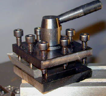 4-Way toolpost
In theory, you can mount four different tools in the toolpost and rotate it around to select the tool you need. In practice, it gets a little cumbersome with more than two tools, but there probably are owners out there who use four tools.
On the underside of the toolpost, there’s a detent and spring mechanism that indexes the toolpost so that its sides line up with the sides of the compound.
Tailstock
The tailstock rides smoothly along the ways and locks into place by means of an acorn nut and wrench. With nicely etched calibrations in both mm and inches, the tailstock barrel makes it easy to drill holes to a desired depth.
For operations such as turning between centers, a lever locks the barrel tightly in position. A #2 Morse taper holds drill chucks, arbors, reamers and other accessories as needed.
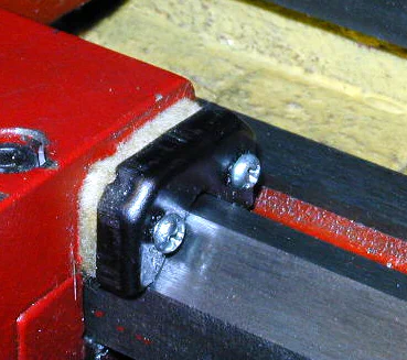
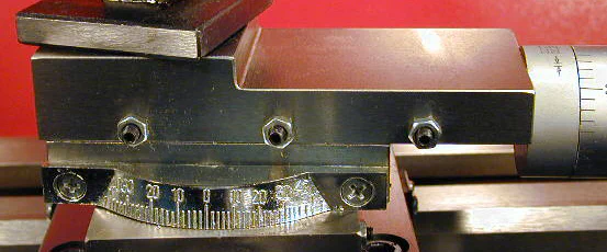
 For turning long tapers, the tailstock can be shifted off-center, by loosening two easily accessible locking screws on the back side of the tailstock.
A small scale helps you to gauge the amount of offset and reset the tailstock on center when you’re done turning tapers. Although I’ve never tried it, you could also use this feature for drilling off-center holes, say for example, to make bolt hole circle on a small flange.
Update 04/04/11: A reader, obviously much sharper than myself, pointed out to me that drilling with an offset tailstock, as proposed above, would not work.
After careful deliberation, it soon became obvious to me why. Duh.
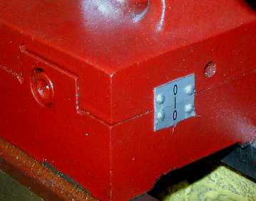 Tailstock offset feature
Due to the limited bed length on the 7x10 and 7x12 lathes, I got into the habit of removing the tailstock when I wasn’t using it, to provide more freedom of movement and ease of access to the carriage.
This lathe is long enough that you can leave the tailstock in place and still have room to work. The extra length also comes in handy when drilling with a long drill bit - or even more so when reaming, since chucking reamers tend to be longer than drill bits of the same diameter.
Conclusion
This is a nice machine. It provides more length - 17% more than the 7x12; 75% more than the 7x10 (which is really a 7x8) - and more power from the larger size motor than the smaller mini-lathes.
Strong torque at low RPMs is a great feature when tapping and threading, and this machine offers more than any 7x lathe that I’ve tested.
Lots of oil ports, sealed by spring-loaded balls, plus the way wipers, help to ensure that the ways and moving parts stay well-lubricated, an important factor in the performance and life of the lathe.
Upgraded safety features, such as the chuck-cover interlock, reset to zero before starting and spring-loaded chuck key, make this lathe safer to use than earlier 7x models which lack these features.
Naturally, anything that improves safety is well worth having.
Fit and finish were very good. I was especially impressed by the nicely finished quality of the cross-slide and compound bearing surfaces. These are important since they contribute to a smooth and precise finish on your work.
If you have too much slop - or too much tightness - in these areas, it will make the lathe more troublesome to work with and reduce the quality of finish on your work.
Plus, a tight-fitting, smooth-sliding lathe just feels good to work with.
You can find them at the Big Dog Metal Works online store. Check ’em out!