X3 Spindle
Attempt to Fix Excessively Long Alignment Pin
After cleaning up the X3 mill, and anxiously getting ready to make my first test cuts, I discovered that none of the R8 collets or end mill adapters that I had purchased for the mill would fit into the spindle.
The only tool that would fit was the arbor and chuck that came with the mill. About an inch and a half up inside the spindle there’s a small pin, about 1/8″ in dia that extends out from wall of the spindle by about .070″. Apparently, the pin was extending out farther than it should. Here’s a photo taken looking up into the mill spindle.

I noticed that the groove on the side of the drill arbor was deeper than the grooves on my other R8 tooling, so I concluded that the guide pin in the spindle must be sticking out too far. Just to check this theory, I measured the depths and widths of the grooves on several tool holders. Here’s what I found:
| Collet or End Mill Adapter | Groove Width | Groove Depth |
|---|---|---|
| Drill chuck adapter | .157 | .168 |
| 3/16″ EMA | .154 | .092 |
| 3/4″ EMA | .154 | .082 |
| 3/8″ EMA | .154 | .087 |
| 3/8″ collet | .155 | .064 |
| 1/2″ collet | .156 | .066 |
Clearly, the drill arbor has a much deeper groove than any of the other tooling, so it could accommodate an overly long pin. The groove is also slightly wider, but only by about 0.003″. Later on this seemed more significant.
At first, following a suggestion from Chris Wood of LittleMachineShop.com, I attempted to use a Dremel tool with a grinding bit to grind down the alignment pin by a small amount.
I tried this, but found that I could not really tell when I was grinding down the pin and when I was simply gouging the side of the spindle wall, since there’s no way to see in there when the Dremel tool is inserted. Even if I could see, there’s not much room to work, so it’s a tricky operation.
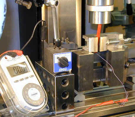
I decided to call it a day, before I messed things up worse. Tossing and turning in bed all night, I realized that I could take advantage of the XYZ table controls to control the Dremel tool with some degree of precision. So next day, I set things up a shown in the following photo.

What we have is a Dremel tool with grinding stone mounted in a large machinists vise turned on its side. The vise is sitting on a pair of V blocks to provide clearance for the power cord. On either side of the vise are 2x4x6 blocks used as supports for the clamps that clamp the vise to the table.
I used a slightly modified version of the setup to visually inspect and measure the offending pin. In this setup, a needle-like electrical probe connected to my digital multi-meter is used to measure the height of the pin. The meter has an audible electrical continuity tester; i.e. it beeps when the two test leads make electrical contact.
I connected one test lead to the test setup (you can just see it attached to a step block in the left edge of the photo above) and the other lead to a home-made probe that has a needle for a probe tip. In the photo below, you can see the red probe with the needle extending up into the spindle.
The idea was to get the probe lined up with and just making contact with the surface of the pin. I used a mirror mounted on a magnetic base, along with a small high-intensity lamp to look up into the spindle while getting the probe lined up.
Once the probe just made contact with the top of the alignment pin, I zeroed the Y-axis dial. Then I raised the mill head so that the test probe needle just cleared the edge of the alignment pin and turned the Y-axis handwheel until the test probe contacted the wall of the spindle.
This reading gave me the height that the alignment pin was extending from the spindle wall: 0.070″. I used a similar technique to measure the distance of the alignment pin from the bottom edge of the spindle so that I would know how far into the spindle to advance the grinder.

That being done, I mounted the Dremel tool and set about grinding the pin down. I ground it down by about 0.010 at a time, stopping to test the fit of various tools after each grinding session. No luck: the tools still would not fit properly even after the pin had been ground down from 0.070 to 0.040.
So, I am now coming to the conclusion that the problem is not the height of pin, but the diameter being a little too large. That’s a harder problem to fix, too, and I currently don’t have a plan for how to do it.
Well, it was kind of fun fooling around with this setup, and I learned some things that will probably be useful on some other project. But, at the end of the day, literally and figuratively, I still can’t use my X3 mill – and THAT is annoying!
The Saga Continues…
I got some helpful tips from the Lathemaster Yahoo group. For those of you who may not know, Lathemaster is the main (and only, as far as I know) U.S. distributor of the X3 mill. If you want an X3, that’s the place to go.
The Lathemaster Yahoo group is a discussion group that covers several products sold by Lathemaster, but the members there steered me to some discussion about a year ago dealing with a problem that sounded very similar to mine.
One additional insight, however, was that it might not be the alignment pin being too large diameter, or extending too far into the spindle, but that the spindle bore itself was a few thous undersize.
I followed the suggestion from one of the posts of painting the end of an R8 tool with layout dye, then inserting the tool into the spindle to see where the dye gets scraped off. This is and old, and quite useful, machinist’s technique. Here’s what I found:

As you can see, there’s a narrow band around the end of the tool where the dye has been scraped off. This marks the extent to which the tool can fit into the spindle bore and provides convincing evidence that, beyond that point, the spindle bore is too small to permit further advance of the tool. Great, now that we know that, what do we do about it?
On the LM group there was discussion about using an automotive brake honing tool to enlarge the spindle bore. I didn’t have such a hone on hand, and suspected I would waste the day if I tried to find one locally.
It seems that the automotive shops in my area now sell only a limited selection of tools, but you can find tons of air fresheners, seat covers and custom wheel covers. So much for the status of home auto repair.
Another post, I believe, mentioned the use of valve grinding compound to enlarge the bore. Now, that I did have on hand, and had used it with success on some other projects, so I decided to give it a try.
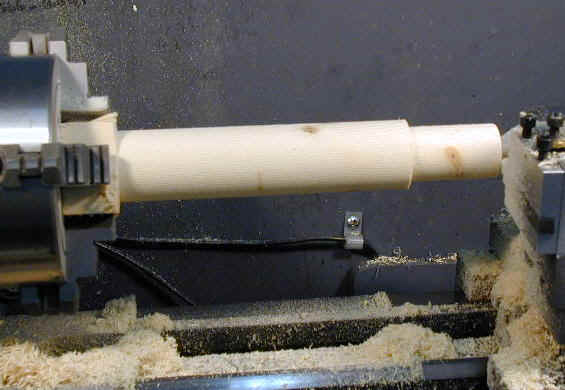
Now I won’t claim to be very experienced when it comes to using valve grinding compound, but I decided that I needed a wooden tool to work the compound around in the spindle. I turned down a handy-looking tool from a section I cut from a 2×4. I tried to shape it so that it would not snag on the alignment pin.
Here it is being turned on the mini-lathe.
And the finished tool:
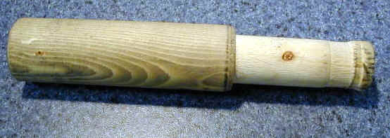
I won’t go into a lot of detail on this effort, other than to say it was a complete failure. In spite of my efforts, the tool kept snagging on the alignment pin, tearing up the end of the tool in the process. I definitely would not use this tool under power, and it was evident that it would take a very long time, if ever, to remove enough metal by turning it manually.
Next idea: why not bore out the spindle using a carbide tipped boring tool? Well, why not? So I got set up for this and it looked pretty promising for a while.
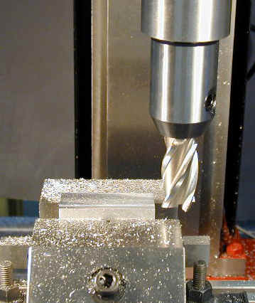
Setup was pretty simple, since all I had to do was clamp the boring tool into the V-groove of the vise that was already in place. I did some measurements and calculations to make sure that the tip of the boring tool would clear the alignment pin.

I insulated the vise from the mill table by inserting electrical tape under the clamps – you can see a small piece of yellow tape in the photo above. This enabled me to use the audio continuity tester on my meter to determine the precise point at which the tip of the boring tool contacted the wall of the spindle. Then I could zero the X-axis handwheel and measure directly on the calibrated dial.
Despite it’s promising beginnings, this setup did not do the job either. I would bore for a while, then move the mill head up and test with a collet or end mill holder. Progress, if there was any at all, was very slow. I concluded that the spindle must be pretty hard metal and that the carbide bit was no match for it.
So, we all know how to deal with hardened metal right? Bring out the grinder again. Trouble was, the grinding tool could not reach far enough up into the spindle to reach the area above the alignment pin where I needed to work.
Ah, Sweet Success!
After sleeping on this problem (again), I came up with an idea that I thought might work. I made a little extension shaft for the Dremel grinding tool. This was nothing more than a short length of 1/4″ dia. aluminum round stock, drilled and reamed to 1/8″ at both ends.
Into one end, I inserted a length of 1/8″ drill rod, held tight by a few drops of Loc-tite. I actually drilled and reamed the other end a little under 1/8″ so that the grinding tool was just press-fit into place.
I toyed with the idea of adding a little 0-80 set screw, but it seemed like a lot of trouble. Anyway, I couldn’t find my 0-80 taps, so I pressed on regardless. As it turned out, it worked fine with just the press fit.

A potential problem with this setup was that I could not use the beeper on the meter to tell when the tool contacted the wall of the spindle. Fortunately, because of the narrow extension shaft, I could see up into the spindle bore pretty well using the little mirror and high-intensity lamp. Here’s what I could see:

This photo shows a cylindrically-shaped grinding tool that I started with. After a few passes with this tool, it became apparent that I was not reaching the lower edge of the area that needed enlarging. I couldn’t bring the grinding tool any lower without hitting the alignment pin.
Fortunately, I had another grinding tool with sort of an acorn-shape. This reduced the contact surface to a smaller area and enabled me to reach the lower part of the bore. At low speeds on the Dremel, the grinding tool would vibrate and precess in a small arc, rather than running true. I found that if I switched to top speed, this problem went away, or was a least no longer visible.
Using the mirror, I could easily move the grinder into position visually. Once it was in place, I turned on the Dremel tool, then turned on the mill, rotating counterclockwise so that it would oppose the rotation of the grinder, and set it to full speed on low range.
Then, watching in the mirror, I carefully advanced the X-axis handwheel until the grinder just touched the surface of the spindle. I then used the spindle handwheel to move the grinder up and down, being careful not to descend down far enough to hit the alignment pin.
What was particularly satisfying about this approach was that I could literally see that it was working. In the mirror I could watch metal being removed on each pass. After working the spindle up and down a few times, I withdrew the tool, turned off the Dremel, turned off the mill, then raised the mill head all the way to the top of the column so that I could insert collets and end mill adapters to gauge how much progress was being made.
I was also careful to clean the bore to remove any grit so that it would not scour the spindle or tooling. I did this by squirting some oil onto a gun-cleaning patch and running it up and down the bore on the end of my finger.
From the layout dye on the top of the tooling, I could see that the tools were now advancing farther into the spindle. It turned out to be a lengthy process, since I did not want to risk removing too much metal at once.
As I like to say, it’s much easier to remove, than to put back. I would grind a little more each time, then check progress. On each pass the tools would fit a little farther into the spindle, but I’m guessing that I was only removing a few 10ths on each pass. One by one, depending on the exact diameter of the its shaft, each of the toolholders started to slide up into the spindle.
The only remaining issue, at this point, was how far to take it before calling it “done”. I decided to continue until most of the tooling would fit without being forced. Then, for the few extra-stubborn ones, I mounted them in the mini lathe and polished the tops of their shafts using #400 wet-dry sandpaper. This did the trick: they now fit slick as a whistle.
Now I just need a chip shield and a power feed.
So, it took me about three days to fix this “little defect”. Otherwise, I have to say that I’m pretty impressed by the quality of the X3 mill. If I put it into perspective, there were a lot more “little defects” on the mini-lathe and mini-mill, and I spent a lot of time getting them to a point where I was really satisfied with them. Now I’m anxious to make a few chips before the holiday ends.
Update from Sieg Industrial
Regular readers of this site know that Sieg sometimes provides products for me to review. That can sometimes be risky for them, because I strive to “call ’em as I sees ’em”, that is, I try to be truthful and objective when I see a flaw, but also to give praise when I think it is earned.
One thing I like about Sieg is that, when a problem is reported to them, they don’t try to make excuses, they offer solutions.
I have been impressed by Sieg’s managers, because they have continued to send evaluation products to me, even though I have been pretty blunt about some of the flaws I have found. To their credit, Sieg has been responsive in correcting the problems when I find them – or when any of their customers find them.
This is a key component of customer service: understanding and responding to the needs and interests of those who buy your products. Sieg has earned my respect in this area.
So, to set the record straight, I received my X3 mill fromSieg almost a year before I set it up and wrote this article. Usually, when I get a new tool to try out, I want to set it up, get it working and write a review within a few weeks. In this case, however, my shop wasn’t ready, so I had to wait.
As it turned out, not long after the shop was finished, I had to undergo some major surgery. By the time I recovered and was back to setting up the shop, nearly a year had passed since I received the mill.
I just received word from Sieg that the flaw that I am reporting on here, was corrected by Sieg not long after my mill was shipped from their factory a year ago, so it was only a few of the early production mills that were affected.
Bottom line: this is a very nice mill and Sieg stands behind their products. I can recommend both the product and the manufacturer without reservation.
