In January, 2000, I bought a mini-mill from Grizzly to complement my 7×10 mini-lathe. Learn more about the 7×10 at my mini-lathe page.

I have been pretty happy with the Grizzly mini mill but whenever I use it to mill a long piece of work, say 4″ or longer, cranking the X axis by hand becomes tiresome, so I set out to add a power feed.
On a project like this, I have a good idea what the end result should be, but can’t conceive all the details until I start building, so I just jump in and work through each step as I see what the next problem is. Usually, the first solution ends up being a prototype and then I build a second one from what I learned from the first one. This method is not for everyone, but works for me. So consider this one to be the prototype 😉
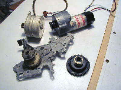
I salvaged an old DEC LA120 printer from the trash at work. At first I thought I might use the electronics as well as the mechanical parts, but I decided to trash the electronics. A few years back I hacked the electronics of an Epson printer to drive the stepper motors, but in that case I had a technical manual and circuit diagrams so the task was manageable. Without the tech info, I decided I would probably not get very far with the DEC printer.
I did, however, salvage a hefty stepper motor, a 24V DC servo motor and some nice gears.
Driving a stepper motor is much more complicated than powering a DC permanent magnet motor so, for now at least, I decided to use the DC motor. Later on I may use a stepper motor to enable software control. Here’s a close-up of the motor label:

The printer was an old platen type (rubber roller) for continuous feed paper. The stepper motor drove the gear train for the platen and the DC motor drove the print head back and forth.
Since I wanted to use the DC motor with the gear train, I had to first remove the toothed pulley from the DC motor shaft and replace it with the gear from the stepper motor shaft.
Not having any gear pullers on hand, I milled some notches in 3/16″ aluminum sheet and slid these under the pulley and gear, then placed them loosely in the vise for support and used a pin punch on the shaft to drive the gear/pulley free.
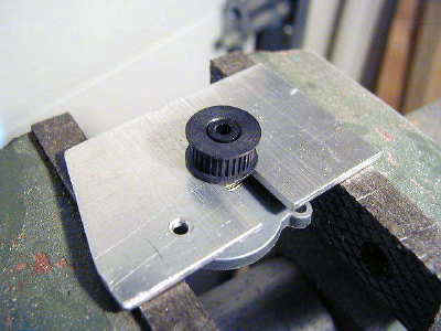
Next I pressed the brass gear onto the shaft of the DC motor. The shaft of the stepper motor was larger than the shaft of the DC motor so I turned a brass bushing which is press fitted into the gear hole. I don’t have an arbor press, so I use my bench vise as a press.

The next step was to add an extension shaft to the left end of the leadscrew. First, I removed the table as follows:
- Loosen the lock nuts on the gib screws, and the gib screws
- Crank the table all the way to the left until the lead screw comes free from the nut
- Carefully (heavy) slide the table free from the dovetail
- Remove the two nuts from the end shaft at the the crank handle
- Remove the crank handle from the shaft (mine was pretty tight)
- Remove the lead screw from the bearings
The handle engages with a key. The leadscrew is supported by two sets of thrust bearings.
Now I drilled out the end of the leadscrew to accommodate the extension shaft. For the shaft, I used 3/8″ dia. drill rod. I decided to turn down the end of the extension shaft to a few thous under 5/16″ and drill and ream the lead screw to 5/16 about 1/2″ deep.
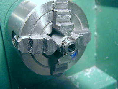
I mounted the lead screw in the 4-jaw chuck, surrounding it with a piece of thin aluminum to protect the threads, then carefully centered it using a dial test indicator:

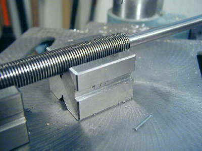
Here’s the end of the leadscrew after drilling and reaming…
and the end of the shaft turned to 5/16″ minus .002.

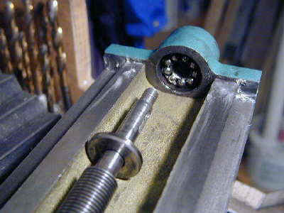
Now we drill a small hole through the diameter of the leadscrew with the shaft inserted. This hole accommodates a pin (I use a small brad which you can see on the drill press table) to lock the shaft and leadscrew together.
Now we make the end plate that will replace the stock end plate on the left end of the table. The tricky part is getting the hole for the shaft to line up as closely as possible.
I measured and drilled pretty carefully, but when all was said and done, I ended up milling out the screw holes into fairly large (3/8″) slots to be able to adjust the end plate to minimize binding of the leadscrew. This is important since the leadscrew tends to bind on its own, even before constraining the left end.
I’m open to advice on how to do this better… (and anything else, for that matter).

The tapped holes in the bottom of the plate are left over from a previous project – they are not used for the power feed.
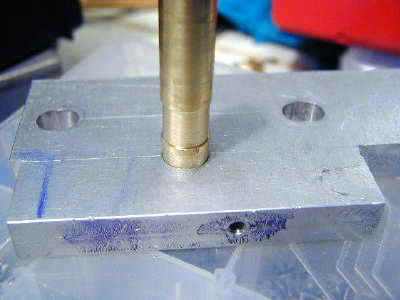
I turned a brass bushing with 15/32 OD and .377 ID to act as a bearing for the shaft where it passes through the end plate. I left a lip .500 OD to seat the bushing when it is press fitted into the end plate. I also made a little tool for inserting and removing the bushing, since I had to do this several times. With a little light oil, this makes a decent bearing, although an oilite or ball bearing would be better.

Here’s the tool in action pressing the bushing into the plate:
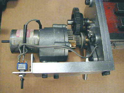
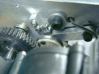
The next photo shows the first test setup where I ran table under power. As you can see, the motor is mounted on a plate that is bolted at a right angle to the table end plate. You can see my 7×10 lathe off to the left.
It is bolted down to the table and, for now at least, made me decide to mount the side plate on the front side of the end plate since the side plate would run into the lathe if I mounted it at the back of the end plate.
For anyone else, I would recommend mounting the side plate at the back, but I did not want to get sidetracked with having to move the lathe and other stuff off to the left side of the lathe (not visible).
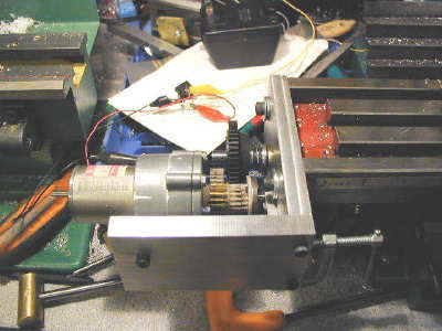
In the background you can see the 24V AC transformer (wall wart) and some test leads running to and from a bridge rectifier. This provides 24VDC for testing purposes. Also visible is a small C-clamp which is holding the middle gear of the gear train in place for testing.
I later had to cut the corners away from the end plate and side plate (you can see this in the previous picture of the end plate) to keep them from running into the rubber chip guard and its underlying metal support arms. Mounting the side plate in the back would alleviate this problem. Maybe it would have been easier to move the lathe?… :-0
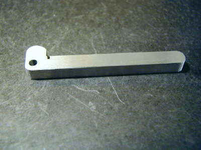
Here’s the idler arm that supports the middle gear of the gear train.

My original idea was to have this arm engaged by a tension spring so that I could disengage it when power feed was not needed. During testing this did not work out too well – the gears tended to mesh too tightly going one direction and too loosely going the other direction.
I’m now working on a cam or some other solution for engaging these gears. Here’s the spring-loaded idler arm arrangement:
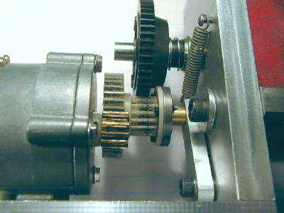
The idler arm is bolted into a tapped hole with a lock nut on the back side of the end plate. The bolt is tightened just enough to remove slop while allowing the arm to swing freely. There are washers on either side of the idler arm – the one in back provides clearance from the end plate.
Progress
I made a little cam lever from aluminum plate. First I cut out a rectangle and then cut away a section on the bandsaw to make an L-shaped piece.
I then rounded the cam on the disk sander and drilled a hole around which the lever pivots on a 6-32 hex head screw between two fiber washers which provide friction to hold the lever wherever it is set. The 6-32 screw goes into a tapped hole with a lock nut on the back side of the mill table end plate.

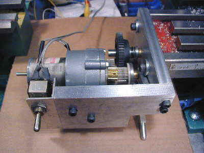
The lever can be moved up and down to engage and disengage the idler arm gear. When disengaged, the table is free to move with the hand crank.
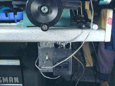
I have also mounted a 3-position DPDT switch on a piece of aluminum angle on the left side of the side plate, near the motor. This switch works just like the direction control switch on the mini lathe. The center position is OFF, UP is left and DOWN is right.
Motor Speed Control
I played around with a motor speed control from the Radio Shack Science Fair Projects mini engineering book. It uses a 555 timer chip as an astable multivibrator to gate a power mosfet. It worked, but did not provide a wide enough speed range, so I put it on the shelf for now.
Next I experimented with a cheap light dimmer module (about $4.00 at Home Depot) between the AC and the 24V transformer. You really aren’t supposed to use this type of dimmer with inductive loads like motors and transformers – they are intended for use with incandescent lights – but I have been using one for over a year to control a heating element via a transformer and it has worked fine.
It worked fine in this application, too. I also bought a different type of speed control intended for ceiling fans – it was about $13 – but it did not provide as wide a range of control and (strangely?) is set up so that clockwise is slower (what else in the world works this way?)
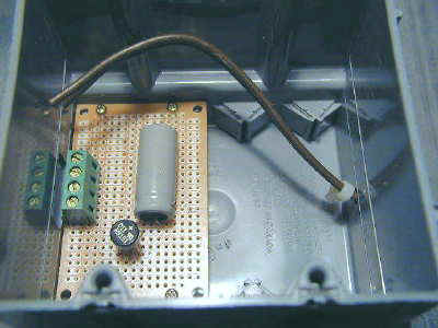
So, for now and maybe forever, I decided to go with the dimmer control. I mounted the bridge rectifier along with a filter capacitor (1000uf @ 35v) on a small Radio Shack experimenters board and mounted this in a dual-outlet wiring box.
An AC cord comes in through a hole drilled in one side of the box and connects to the dimmer and one side of an AC outlet. The other wire from the dimmer goes to the other (black /gold screws) side of the outlet.
The 24V transformer/power cube plugs into the outlet and the wires from the secondary go down through a hole milled in the side of the outlet box to the circuit board connectors. The DC comes out through the same hole and goes to the motor.
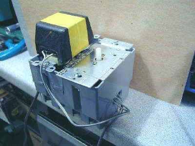
The original 24V transformer turned out to be too small and was getting quite warm when powering the table under actual cutting conditions. I replaced it with a more robust one which stays pretty cool. I mounted the power supply box under the edge of the workbench.
The power cable runs up to the front edge of the mill table where it is held in place by a plastic channel made from acrylic plastic.
The channel was made by cutting a piece of 1/8″ acrylic about 9″ long and then gluing two narrow strips to one side, leaving a gap in between to form the channel in which the cable rests.
The channel is attached to the front of the mill table by 3 2-56 stainless screws. I first tried gluing it using RTV silicone sealer but found that I needed to remove it in order to make mods to the power feed.
I replaced the 3-position switch with a miniature version from Radio Shack. The new switch is mounted sideways so the the direction of the toggle is the direction of table movement. For the spatially impaired, this helps keep things moving in the right direction.

Limit Stop for Idler Lever
It turns out the there is a fairly precise point at which the gears are engaged just the right amount. I could find this point by feel and by the sound of the gears when engaging the idler lever, but I decided to add a limit stop so that I could set the optimal point and then just engage the lever up to the stop.
The stop is an L-shaped piece of aluminum with a stainless 4-40 screw mounted in a tapped hole. A spring under the head of the screw keeps it from moving due to vibration.
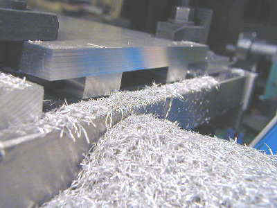
Cutting Edge Results
Well, the ‘prototype’ version has turned out to work pretty well, so I may not make a ‘final’ version. Here’s an example of the kind of work that is a breeze using the power feed: