SX2 Mini Mill Air-Spring Conversion
Torsion Spring Arm
Early models of the mini mill, before around 2002 or so, used a compressed-air spring to offset the weight of the head. The air spring cylinder is mounted inside the hollow column and the piston moves in or out as the head is moved.
Since that time, including on the new SX2 model, the air spring has been replaced by a spring-loaded torsion arm on the left side of the mill.


For my needs, I like the air spring better. The torsion arm does a pretty good job when the head is close to the table and the coil spring is fully compressed, but as the head is moved up the column, the spring unwinds and applies less offsetting force to counterbalance the head.
Near the top 1/3 of the column, the spring offers little support and, unless the gibs for the head’s dovetails are maintained to a snug fit, the head can slide down the column, causing the 3-spoke handwheel to spin, possibly whacking you in the arm or hand.
There does not appear to be any way to adjust the spring tension to correct this tendency, so you need to be sure to keep the gibs snugged up.
My other gripe about the torsion spring is that it gets in the way of making one of my favorite mods on my old Grizzly mill: an adjustable dial indicator to measure depth of a Z-axis cut or a drilled hole.

Maybe it could be moved to the right side of the column, but then the mounting bracket for the upper end gets in the way of the gib screws. And besides, that’s where my Y-axis DI is mounted.

Luckily, you can buy an air spring kit to replace the torsion arm. Currently priced about $49.95, it’s a good deal if you can’t find happiness with the torsion arm. This article is about how I replaced the torsion spring with the air spring kit from LMS.
The Air Spring Kit
As it comes from LMS, the air spring kit is a pretty easy conversion for the X2 model mini mills. You merely lay out and drill a few holes as specified in the illustrated instructions and with about an hours work, the conversion is done.
In my case, however, I wanted to use it with Sieg’s new SX2 mini mill with the new brushless motor and belt drive spindle. I soon discovered that I needed to make a custom bracket and apply a little ingenuity to use the air spring on the SX2. But I got it done, and I’m really pleased with the result.
The air spring kits includes:
- The air spring (made in USA)
- A replacement rack, longer than the stock rack for greater range
- Mounting brackets and screws
- Instruction manual


Installing the New Rack
The new rack is longer than the original, allowing for a larger range of head movement.

Remove the plastic stop bushing that limits the upward movement of the head. The threaded hole will be used for the top screw of the longer rack.

Before removing the stock rack, make sure that the gib screws for the head are snugged up and that the head is securely locked in place using the locking handle. Otherwise, once you loosen the rack mounting screws, the head could slip rapidly down the column.
With the head lowered and locked, remove the top mounting screw. Then raise the head, lock it, and remove the lower screws. Turn the head handwheel counterclockwise and the rack will be ejected out the top of its mounting channel.

Reverse this process to install the new rack.
On the X2 model lathes with the large brush type motor, there’s plenty of clearance behind the motor for attaching the mounting bracket for the air spring, but on the new SX2 with the brushless motor and belt drive, the motor mount casting extends nearly all the way back to the column.

You can’t just mount the air spring mounting bracket on top of the motor mount because the belt tension adjusting screws are right in the same location. Therefore, I found it necessary to make a squared-off inverted “U” bracket to span across and screw into the sides of the motor mount casting.
This leaves clearance for the belt tensioning screws, and access holes drilled into the cross-bar of the U-bracket provide access to adjust the belt tension when necessary.

Making the U-Bracket
I made the U-bracket from a solid piece of aluminum about 1″ x 2 1/2″ x 4″ that I found in my scrap box.
Not wanting to reduce the entire center section of the workpiece to a pile of chips, I first cut out the center on the bandsaw, leaving just the outer rectangular U-shape that I needed for the bracket.
In order to turn the bandsaw blade at the bottom of the cut, I had to work my way down one side using a series of angled cuts until I had a notch wider than the width of the blade (as viewed from the side).


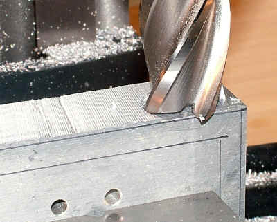
Next, I cleaned up all of the inside surfaces of the bracket using a 1/2″ end mill with an extra long 3″ cutting face to reach down into the inside of the U. I made the final cuts to the sides carefully so that the bracket would fit snugly over the motor mount casting.

When I started planning the dimensions of the bracket, I wasn’t exactly sure how I was going to mount it to the head, so I made it somewhat wider than was really necessary. Later on, I had to mill out a notch to provide clearance for the rack on the column.
In retrospect, I could have just made the bracket narrower, so that the notch would not be needed. That’s what I call “the evolution of product design.”, but probably better known as “cut and try.”

When measuring for the placement of the notch, I didn’t notice that the rack is not centered on the column – it’s actually closer the left side – so I had to make the notch a little wider than planned.
It may be possible to make a functional bracket by just bending some reasonably heavy gauge steel plate. Of course that would not be as much fun, and would not give me an excuse to use the mill.
Mounting the U-Bracket
About the only obvious place to attach the bracket is to the sides of the motor support casting. I played around with the positioning until it looked “about right’, then scribed some reference lines on the sides of the casting.

To lay out the positions for the corresponding holes in the U-bracket, I made a temporary jig to make sure that the bracket was even on both sides of the motor mount casting.


Next I laid out, drilled and tapped 8-32 threaded holes in the sides of the casting. For reasons that I imagine are pretty obvious, I could not drill the holes using the mill. Fortunately, I had another mini-mill sitting on the bench. 🙂 The holes, of course, could be drilled on a drill press, if you have one, or using a hand drill, if not.


Installing the Air Spring
Before removing the torsion spring assembly, I made sure that the gib screws for the head were very snug so that the head would not come crashing down without the support of the torsion spring.
Of course, you want the head all the way up to relieve tension on the torsion spring before loosening the retaining bolt.


The air spring kit includes a steel rod, about 1/2″ dia. x 11″ long, threaded at both ends. One end of the rod mounts to the U-bracket, using nuts on both sides of the U-bracket cross-bar; the other end threads into a short cross-bar that in turn attaches to the upper end of the air spring.
With the U-bracket in place, installation is similar to the standard procedure for the classic style X2 mini-mill. The difference is in the placement of the mounting holes, since the air spring is now a few inches higher, due to the U-bracket, and probably not the same distance from the back of the column that it would be in using the standard X2 mounting.
For convenience, I tried using the existing holes in the column where the torsion spring hardware had been mounted. A 5/16″ x 5″ bolt was just the right size to pass through the hole in the end of the air spring strut, but smaller than the diameter of the existing holes. I turned down a pair of bushings to compensate for the diameter difference.

This approach worked, more or less, but, since the holes were not lined up with the air spring, the air spring was slightly tilted and in turn cause the steel riser rod to tilt, which seemed to me to be an undesirable situation.
So the next goal was to drill some new mounting holes in the sides of the column so that the air spring, and thus the riser rod, would be vertical and parallel to the column and to each other.
After some measuring, I marked the locations for the new holes on the column and drilled them. I intentionally positioned the holes a little high, so that at its maximum extension the air spring allows the head to move a little above the top of the column.
I did this to allow for maximum clearance to the table for milling and drilling operations. A 5/16″ x 4 1/2″ bolt with a lock washer is just about the right length.

I haven’t done it yet, but I’m thinking about making a pair of spacers to go on the bolt on either side of the air spring. I may add the spacers if I run into problems with the air spring shifting from side to side on the bolt.
Getting the spacers in place will no doubt prove to be something of a puzzle, since the bolt is way down inside the column. I’ll save that project for a day when I have a good sense of humor. (Note: in the standard installation instructions for the X2 mill, the bottom end of the air spring mounts to the back wall of the column, so spacers are not needed.)
