Mini Lathe Modifications
Many ingenious modifications and improvements to the minilathe have been devised by the active community of users. I was originally hoping that this page would be a place where I could collect them all for convenient access.
However, there are now literally thousands of owners out there and they are coming up with new mods every day, so it is a hopeless task to try to keep up with them all. Unfortunately, links to other sites frequently go out of date as the owners of those sites change hosting services or just drop off the web altogether.
I review the links periodically and update them if I can find a new URL for the site. Readers and site owners often send me updated links and notifications about broken links, which helps me with this process.
Here are some other places to look for information on modifications:
- David Denker’s site – some nice mods
- Varmint Al’s site
- Ty Hoeffer’s site
- John Moran’s site
- Magic Brian’s workshop – mini lathe and mini mill mods
Cross Feed, Compound and Crank Handles
I had some problems with the factory handles that made me decide to replace them with handles I made on the lathe. This was the first mod I made to my lathe.
I also replaced the plastic handles on the carriage feed and tailstock with tapered aluminum handles which have less slop and are smoother in operation.


Brass Saddle Strips
On the underside of the saddle are two iron strips that hold the saddle onto the ways. The stock items are made out of some kind of brittle iron that eventually cracks. Mine cracked, so I replaced them with brass strips milled to the same size as the original strips.


Using the originals as a guide, I used a transfer punch to mark the centers for the mounting holes. These new strips can be adjusted more precisely than the originals so that the saddle has very little slop, thus reducing chatter.
If you don’t have a mill, you can get some steel or brass of the correct thickness and cut it to size with a bandsaw or hacksaw and then finish the pieces using a file.
Custom Tool Holder
My original 7×10 lathe came with a defective saddle – the V-groove on the bottom of the saddle was not square with the lathe ways. I was able to fix this by milling the V-groove, but this had the effect of lowering the saddle by about .020″.
I did not want to use shims under the tools to raise them back up to the correct center height, so I made a new tool holder instead.
I wanted to do this anyway because I wanted to be able to mount my tools flush with the edge of the toolholder so that I could work very close to the chuck jaws as when making a parting cut. Here’s one of several tool holders I made:

As my skills developed, I made quite a few Quick Change Tool Posts (QCTP) of various designs. Detailed plans for the latest version are now available if you would like to make your own.
JW Early’s QCTP adaptation and other QCTP links
Carriage Gear Chip Guard
The gears that drive the carriage by means of the hand crank tend to get a lot of chips and swarf in them.
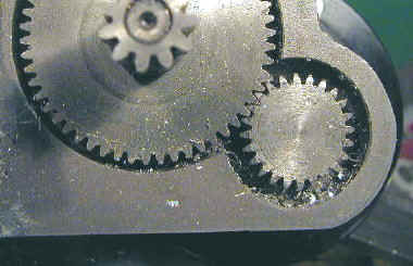
Varmint Al devised a chip guard to solve this problem, but the picture on Al’s site is a side view which doesn’t show much detail. I never really visualized how it worked until Corey Renner posted some pictures of his implementation:

After seeing Corey’s pictures I decided to make one for my lathe. I used acrylic plastic sheet about 1/8″ thick, cut and filed it to shape and bored the hole for the gear shaft on the lathe using a 4-jaw chuck to hold the plastic piece.
It probably would have been easier to bore the hole before cutting the curved edges on the piece, but I didn’t think of it at that time.

On my lathe, the faces of the two gears projected a small amount above the surface created by mounting the chip guard, causing the gears to rub against the surface of the chip guard.
I tried inserting some small washers to raise the chip guard, but this partly defeated its purpose by creating a gap where chips could get in. I solved the problem by facing off a few thous from the face of each gear.
I mounted the cover to the carriage casting by drilling and tapping for 4-40 flat Phillips head screws. Finally, I lubricated the gears with a liberal dose of white lithium grease.

Alignment Guide for Tailstock Clamp
Since the bed of the 7×10 is so short, I remove the tailstock when I’m not using it. The metal plate attached to the tailstock clamping bolt is free to rotate but must be in the correct orientation when the tailstock is reinstalled on the ways.
I added a bolt to keep the plate from rotating so that it stays in the correct orientation. That way I can remount the tailstock without looking at or adjusting the plate. The bolt is threaded into a hole drilled and tapped in the tailstock base and is locked in place by a washer and nut.
I also added a spring to keep the plate pressed down so that it doesn’t jam when I’m reinstalling the tailstock and rounded the leading edges of the plate with a file so that it slide back into place more easily.

Tailstock Cam-lock
This is one of the all time best mods for the 7×10. It’s a fair amount of work to do it, but it makes the lathe much nicer to work on. Mine is derived from JW Early’s design. See my Cam-lock Tailstock page for complete details on this mod.

Nut Keeper for Chuck Nuts
I turned a little post out of aluminum and epoxied it to the control box. I keep the extra nuts for the 4-jaw and 4″ 3-jaw chuck on this post when they are not in use.
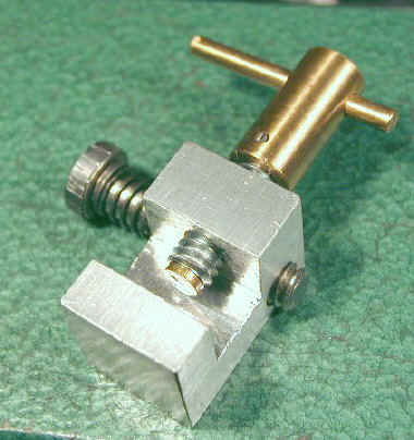
Carriage Lock
I got this idea from Varmint Al, then embellished it with a T-handle. Note the brass plug in the tip of the bolt. The bolt is a standard steel 1/4×20 from which I removed the head and then added the brass extension.
A small brad passes through a hole drilled through both pieces to lock them together.. A 1/4 x 20 hole is drilled and tapped in the saddle casting (remove the carriage from the ways before drilling!) I made this one before I learned how to do threading on the lathe so I just used a commercial bolt.
You could make one from a solid piece of brass and thread it using a die or by cutting threads on the lathe.

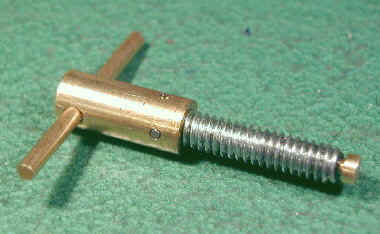
This is a real simple mod and is much better than having no carriage lock at all, but it has the disadvantage that it tends to lift the saddle away from the ways which is undesirable.
I have also published a Premium Content cam lock carriage lock project that applies downward force directly under the center of the saddle.
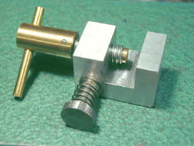
Carriage Stop
Another embellished Varmint Al idea. The carriage stop clamps onto the back side of the ways. It is handy for stopping the carriage when a certain point in its travel is reached – say at a shoulder.
I find it very useful when boring to a specific depth. I added the stop screw so that I can precisely set the stop point after clamping the device to the ways. It also solves the problem of chips jamming between the edge of the saddle and the side of the stop. The spring keeps it from moving due to vibration.
Reducing the Minimum Speed
The minimum spindle speed on the HF 7×10 as it comes from the factory is too fast for some operations such as tapping. Tapping under power is a little risky even at slow speeds since it is easy to break the tap off in the workpiece but, with care, it can be very effective.
The newer lathes have more sophisticated power supplies than the earlier versions and have very good low speed capability right out of the box. Lathes made after 2001 do not require this mod.
Warning: there are hazardous voltages (120 Volts AC and DC) exposed in the speed control box. Do not attempt the adjustments described here unless you are qualified to work with such voltages.
Additionally, since the speed adjustments must be carried out with power applied, shorting out the circuit board is also a potential risk. To minimize this risk, and the risk of shock, use a tool with an insulated handle with a very small metal screwdriver tip. TV alignment tools are ideal for this. Here’s the tool I use:

Jose Rodriquez made a similar tool from a piece of wood dowel and a metal tip.
Note: the following procedure describes the Harbor Freight 7×10 SKU 33684 purchased in 9/99. This description may not apply to other models or later models of the same lathe.
The speed control board is located in the electronics box:
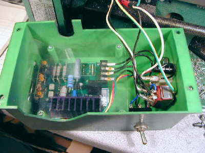
The circuit board is covered by a plastic sheet held in place by 4 screws. This sheet helps keep metal chips from reaching the circuit board. Turn the power box with the opening down and rap it on the benchtop to dislodge any metal chips that may be present, then remove the plastic cover.
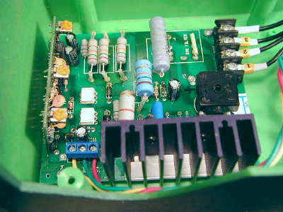
A daughter board is mounted at a right angle on one end of the main circuit board. The daughter board contains two LM324 op amp chips along with the usual resistors and capacitors.
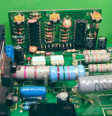
At the end of the daughter board are mounted 3 tiny control pots (potentiometers – just like the main speed control, only much smaller). These pots are sealed at the factory with a covering of black lacquer or glue to keep from shifting. The lacquer covering has been removed here.
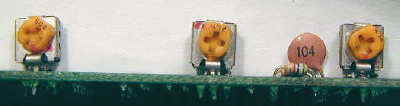
These pots control various aspects of the waveform that drives the motor. With the right settings it is possible to run the 7×10 at 30RPM while maintaining pretty strong torque.
Before changing the settings, mark the original settings by making a small dot on each pot dial and on the fixed edge of the pot using a Sharpie pen or similar tool. It is very important to be able to get back to the original settings as you experiment with these pots. After you have marked the pots, use an Xacto knife or similar tool to remove the lacquer covering from the pots.
Make sure the lathe is set to LO range and minimum speed before you start. With the pots exposed so that you can adjust them, turn the lathe on. Start with the rightmost pot and slowly turn it clockwise – the lathe speed should decrease. If you carefully grasp the spinning chuck and apply pressure, you can feel the effect on the torque.
Move the pot back to the original setting and repeat this process for the other 2 pots until you get a good sense of how they affect speed and torque. After you play with them for a while in various combinations you should find a setting which provides a low speed of 30-50 RPM with good torque. 30 RPM is the slowest speed I have been able to achieve with adequate torque.
If you think of the pots as a clock face, the settings I used are:
- Left Pot – 1 1/2 hrs clockwise
- Mid Pot – No change
- Right Pot – 1 hr clockwise
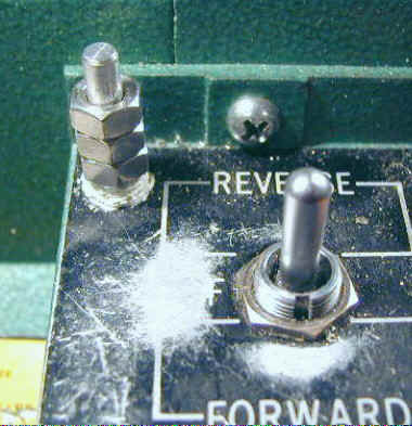
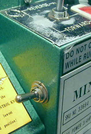
Forward / Reverse Switch Interlock
Note: Minilathes made in 2002 and later have an electrical interlock built in to the motor speed control that requires you to reset the speed control knob to zero when changing directions. Therefore, this mod is not needed on the newer lathes.
Several owners of the minilathe have reported blowing fuses due to accidentally switching from forward to reverse suddenly. Adding a second switch as described here will prevent that problem.
Total cost about $2.50. Total time 30-60 mins depending on your skill level.
You will need:
- A new DPDT switch, Radio Shack part # 275-1533 (part number may be out of date, I’m looking at a 1996 catalog)
- A short piece of wire (3-4 inches) about 20 gauge. (diameter of conductor should be no smaller than the existing wires on the F/R switch).
- A low wattage (25-50 W) soldering iron and solder
- Rudimentary soldering skills

- Unplug the lathe power cord
- Remove the power supply box from the lathe (4 screws) and flip it over (same as for low-speed mod)
- Two wires run from a black plastic terminal block to the bottom two terminals of the F/R switch. On my machine the wires are labeled 1 and 2.
- Unsolder wire 2 from the bottom left terminal of the F/R switch and solder it to the center terminal on either side of the new switch (you will be using the terminals on only one side of the new switch)
- Unsolder the (blue, on my lathe) wire from the top right terminal of the F/R switch and solder it to either terminal on the same side of the new switch as the wire from the previous step.
- Solder a new wire from to top right terminal of the F/R switch to the other terminal on the same side of the new switch.
- Check all solder connections to make sure they are bright and shiny and that you have no shorts between terminals. Be sure, since a short will blow out the power supply and/or motor!
- Drill a 1/2 hole on the left side of the power supply box and mount the new switch.
- Plug the lathe back in and turn it on.
Now both the F/R switch and the new switch must be in synch to change direction. If you are in Forward and switch to Reverse, the motor will not start until the new switch is in the Reverse position as well. Same thing going from Reverse to Forward.
