Mini lathe chuck adapter plate
Introduction
I find myself using the C6 10×22 for most of my lathe work these days. Not that I’ve abandoned the faithful 7×12, but, especially for larger work, it’s just easier to use the C6. It can take deeper cuts without breaking into a sweat.
This weekend, I was working on a project that required a 4-jaw chuck, but the workpiece was too large for the 7×12. The C6 came with just one chuck – a 5″ 3-jaw, and I have not yet gotten around to ordering a 4-jaw and other chucks and a faceplate for it.
Of course I have a 4″ 4-jaw, that I use on the 7×12, but I have no way to mount it on the C6. I’ve even found a few occasions when I wanted to mount the little 3″ chuck on the C6 – so that I could grip a workpiece from a center hole by moving the jaws outward.
For the particular piece I was working on at the time, the jaws for the 5″ chuck were too large to fit through the center hole, but the 3″ chuck would have worked nicely.
Back plates for the C6 are somewhat complicated to make, as you’ll see below, and are not available from any U.S. source that I’m aware of. The Sieg C6, and accessories for it, are not easy to obtain in the U.S.
LittleMachineShop.com carries a few accessories, such as a face plate, which I recently ordered. Grizzly sells a version of the C6 (G0516) with a mini-mill mounted to it, but does not sell the C6 lathe as a separate item.
Update: I just found the C6 listed on the Cummins site (P/N 7900) for $849.99. That’s not a bad price for this lathe, which at 10×21 is a step up from the 9×20.
So I started thinking about making a new backplate for the chuck. I soon realized that it would be a pain in the neck to switch backplates every time I needed to switch the chuck between the 7x and the C6.
Then it occurred to me: why not just make an adapter that makes the C6 spindle “look like” the 7x spindle? That way, I could make just one adapter and mount any 7x chuck – or the 7x faceplate – on the C6. Cool.
That being decided, now I had to make it.
The spindle uses a semi-quick-release design that takes a back plate of special design, with three studs that insert into holes in the spindle. A raised boss on the spindle mates with a recess on the chuck back plate (similar to the arrangement on the 7x lathes) to align the chuck with the lathe centerline.
On the back side of the spindle plate is mounted a plate with “keyhole”-shaped holes. This plate is attached to the back of the spindle such that it is free to rotate through an arc of about 30 degrees.
The chuck bolts pass through the large part of the keyhole, then the plate is rotated so that the narrow part of the keyhole is lined up with the bolts and the nuts are tightened down onto the keyhole plate to lock the chuck in place.
Preparing the Raw Material
I quickly determined that I would need a chunk of aluminum at least 1″ thick by 4″ diameter for the adapter plate.
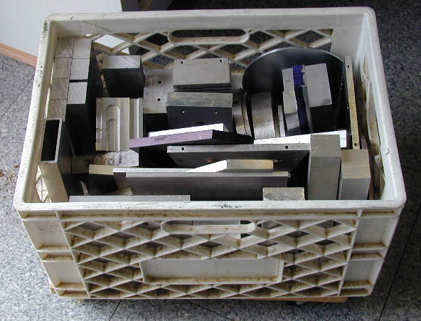
The largest round stock I had on hand was only 2″ dia. There were a few pieces of larger dia. stock in the junk box, but nothing quite suitable for this project, so it became apparent that I would have to cut a section from a large (7×16) piece of 1 1/2″ thick aluminum plate salvaged from the junk yard a few years back.
With my table extension mod on the 4×6 bandsaw, I had nothing to fear.
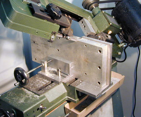
First step was to cut of a piece about 4 1/2″ square. This is a little tricky using the 4×6 bandsaw, but I’ve done this sort of thing before. It’s necessary to make the cut in two operations – one from each side of the stock – to tackle a piece this big.
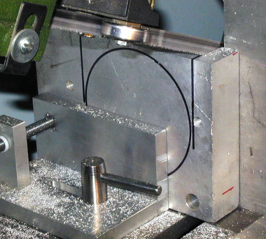
After cutting a suitable sized piece from the end of the block, I made successive cuts to rough the workpiece down to about 4 1/4″ square.
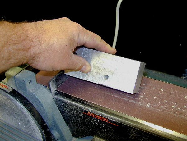
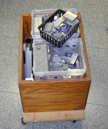
Incidentally, after I cut off each piece of the excess stock, I take the cut off piece and remove the sharp edges on the belt sander, then toss the piece into the junk bin for some future project. Sanding the edges saves me from slicing my fingers on a sharp edge when I’m rummaging through the junk bin at some future time.
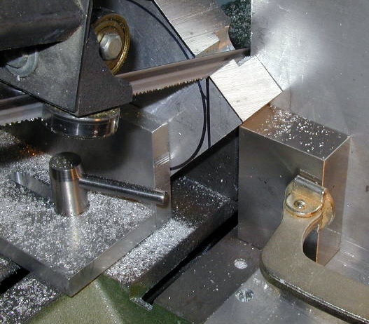
After reducing the workpiece down to a rough square, I marked off the corners and cut them off to form an octagon. The octagonal shape makes it easier to turn the workpiece down to a circle in the lathe. I used a 1-2-3 block clamped to the table extension on my bandsaw to provide some extra support while cutting the corner off the workpiece.
Making the Spindle Recess
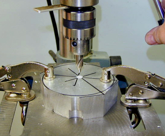
Next, I used a pair of dividers to find the center of the circle, then I mounted the rough workpiece on the drill press and drilled a 5/16″ hole in the center. A bolt through this hole, secured by a nut on the other side, provides a holding point to grip the workpiece in the 3-jaw chuck. Now we can start turning it down to a smooth circle.
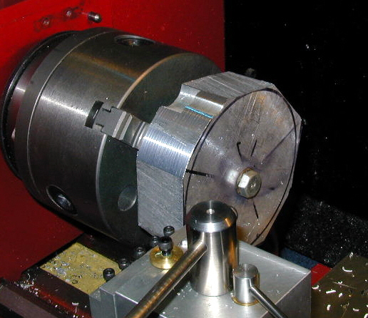
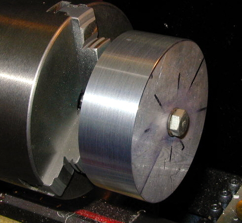
Next I mounted the now round workpiece using the outside chuck jaws. Now we can bore out the recess to mate with the boss on the C6 spindle.
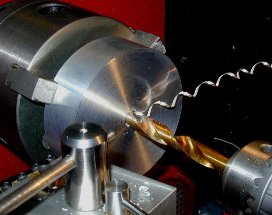
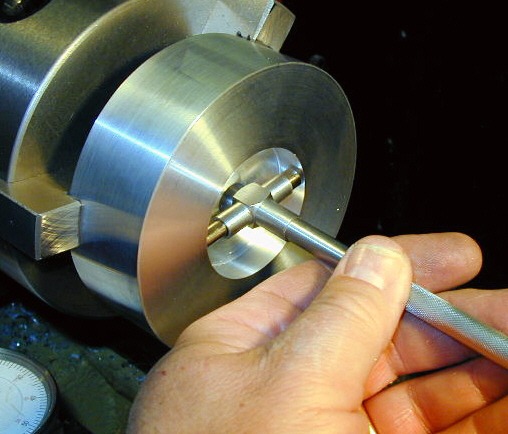
I used a carbide boring tool (one of the type that come in low-cost sets) to bore out the spindle recess. The diameter of the recess is one of the two critical dimensions on this project – the other being the diameter of the raised boss that mates with the chuck – so I proceeded slowly and carefully as I approached the final diameter.
Making the Mounting Studs
The C6 lathe has a semi-quick mount system for the chucks. The nuts stay on the mounting studs all the time, and pass through oversize holes in the lathe spindle. On the back side of the spindle plate, is another steel plate about 3/16″ thick. It has three keyhole-shaped holes in it and the nuts for the chuck pass through the large part of the keyholes.
Then the plate is rotated, bringing the small part of the keyholes under the nuts and the nuts are tightened down. Once you get used to it, it is pretty quick and simple. On the other hand, it complicates the work required to make your own chuck adapter plates because you must make three mounting studs in addition to the back plate itself.
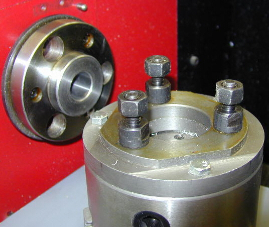
After locating some steel stock of about the right diameter in the scrap bin, I first threaded one end to 10×1.5mm to match the nuts that came with the stock chuck. I wanted to use the same stud diameter and nuts to ensure that the adapter mounted tightly to the spindle.
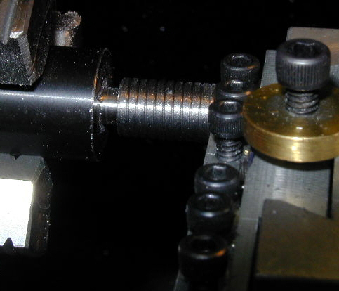
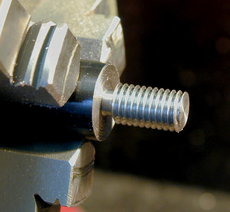
However, on the other side of the stud, that threads into the adapter, I chose to use 3/8-16 threads. Why? Because there was no need to use metric threads, and I don’t have any metric taps in larger sizes.
It was quicker and easier to cut the threads using a die than to turn them using a threading tool. To learn more about cutting threads, see my Premium Content article.
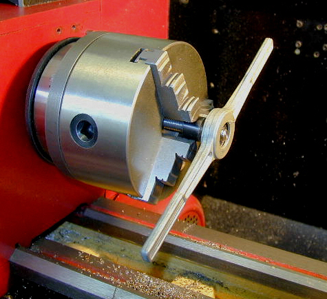
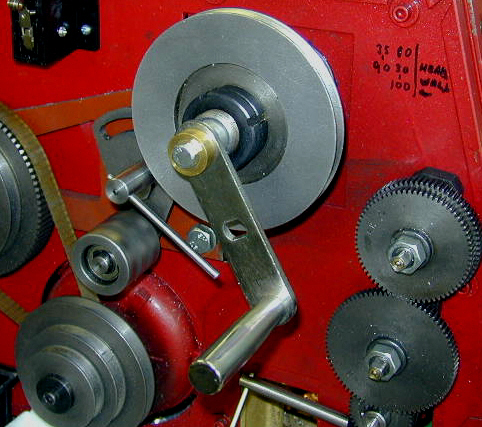
When using a die wrench, as shown in the photo above, the lathe is not used under power. The chuck is used as a convenient way to hold the work and to keep it aligned while turning. The spindle drive belt is removed and a hand crank (see below) is locked into the back side of the spindle to turn the chuck by hand.
For reasons unknown to me, the C6 lathe does not come with a standard threading dial. LMS sells one to fit the C6, and I recently ordered it, but have not received it as of this writing and didn’t have it when I was doing the threading for the stud.
Fortunately, the C6 does have a reversible motor, so you can get by without using a threading indicator by simply reversing the motor (after retracting the cutting tool) after each thread cutting pass.
Unlike the mini-lathe, the C6 lathe does not have a variable speed motor, so, to change spindle speeds, you must stop the lathe and change the position of the drive belt onto one of six pairs of pulleys. The lowest spindle speed is about 60 RPM which is faster than I like for threading.
Also, the larger motor and heavier chuck of the C6 as compared to the mini-lathe, add certain amount of inertia that keeps the chuck turning after the power is shut off. When you’re working up close to the end of the thread, the 60 RPM spindle speed along with the inertia, make it pretty much inevitable that you’ll crash the threading tool into the workpiece at the end of the threaded area.
To avoid this unpleasant prospect, I turned off the motor well before I reached the end of the thread, and used a hand crank to manually turn the spindle for the last one or two threads.
The manual crank that came with my Harbor Freight 43331 winch turned out to be a perfect fit to make a crank for the C6 lathe. I made a compression fitting to hold it into the spindle through-hole. The handle also fits the mini-lathe, since it has the same size spindle through-hole as the C6. So now you have another good excuse to buy a winch. 🙂
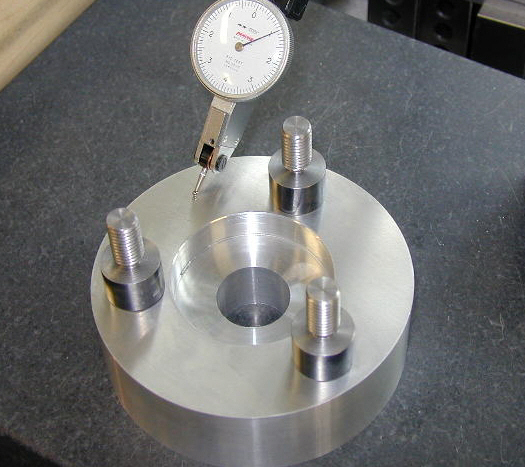
I didn’t have a spec sheet for the stock spindle adapter plate that came with the 5″ chuck. Therefore, to determine the bolt circle diameter for the mounting studs, I mounted the stock chuck on a 6″ rotary table on the table of the Super X3 mill.
After centering the RT under the spindle and centering the chuck on the RT, I offset the table using the X-axis handwheel and indicated on the stud to determine the bolt circle diameter.
Then I used the rotary table to drill the holes for the studs, which I tapped 3/8-16 using a hand-held tap wrench. After mounting the studs into the adapter plate, it was looking pretty nice…
Copying the Mini-Lathe Spindle
With the studs now mounted to the adapter plate, I could mount the whole assembly on the spindle to work on the other side that mates with the mini-lathe size chucks. The next step was to turn the raised boss that mates with the mini-lathe chucks. This dimension is also critical, and the boss must be exactly concentric with the recess on the other side of the adapter.
While turning down the front of the adapter, I took some pretty aggressive cuts. This spun off some really nasty spirals of razor-sharp aluminum. Naturally, I had my safety glasses on, along with an extra protective shield.
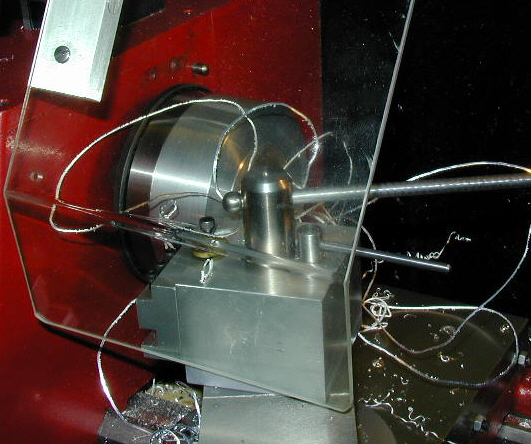
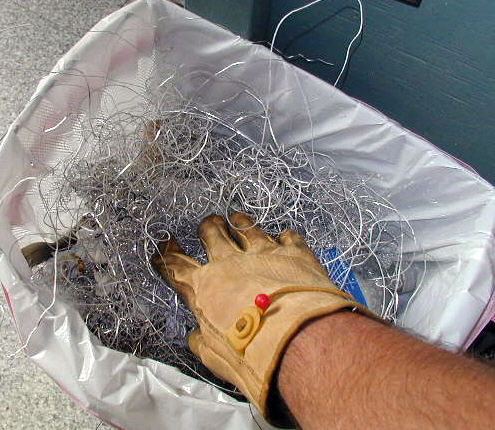
To prevent these shards from building up and getting wrapped around the spindle – which could have created an even more serious hazard – I frequently stopped the lathe and, wearing leather work gloves, removed the excess metal and deposited it into the trash can.
After a while of this, I had the boss turned down to the exact diameter to mate with the mini-lathe chucks.
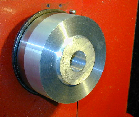
The next set of operations, cutting a deep groove to provide access to place the nuts on the mini-lathe chuck mounting studs, was interesting and challenging. So much so, that I apparently got caught up in the work and forgot to take any pictures of this phase of the work. Oh well, this really wasn’t intended to be an instructional article anyway.
Let me just say that getting smooth surfaces down in the groove was difficult. In order to reach way down in there, I had to extend the cutting tools pretty far out from the tool holder.
This, of course, leads to chatter, which can leave an interesting, but unwanted, geometric pattern on the surface of the work. You can see from the following photo the essence of what had to be done.
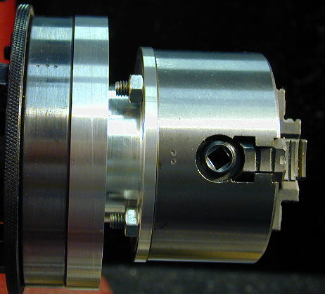
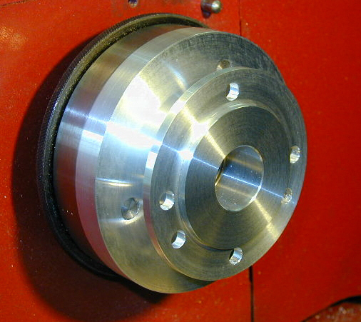
The deep channel behind the front mounting plate provides clearance for the mounting studs and access to manipulate the nuts. I drilled holes for mounting both 3-jaw and 4-jaw chucks, mirroring the bolt hole pattern on the mini-lathe spindle.
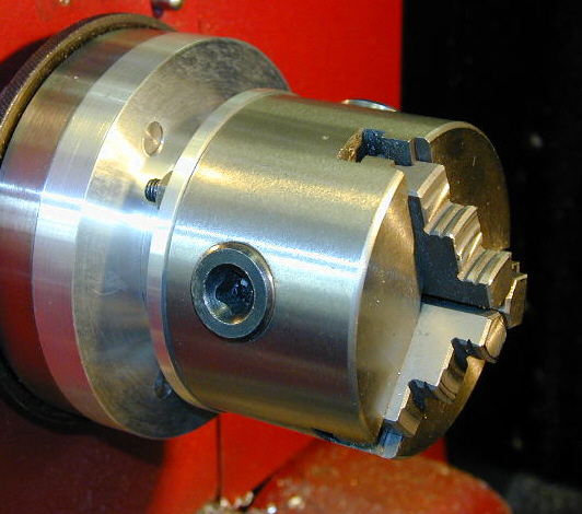
As often happens, this project took much longer to complete that I had expected when I started out. I was thinking it would be 3-4 hours work, but I think it took 10-12 before I was done.
If I had known it would take that long when I started, I’m not sure that I would have made it, but once I had spent a few hours on it, it made sense to keep on going until it was done. As always, I learned some things along the way, so I suppose it was time well spent.
Anyway, this is a hobby, right? So I get to do whatever I want. 🙂
